
Multimeter Clock – Simpson 260

Ever since I setup the CNC machine and built the controller housing I have been playing around with various ideas. Wooden gear projects have been around for a long time, and lots of people have made conventional gear clocks. I wanted to do something a bit different. This project combines some electronics and lots of wood.
**UPDATE** This project is now available as a kit. Please have a look at the Gear Clock Kit page in the online store or have a look at the Gear Clock Kit assembly page for additional assembly information.
The information below is of the prototype version, the CAD DXF and PIC Microcontroller HEX files of the kit version are available here on the kit page. If you are building one I recommend that you make the kit version.
Video
Overview
The heart of the clock is a PIC 16f628A microcontroller (PDF). This microcontroller has an internal oscillator however an external 20MHz crystal oscillator is being used since it will have to accurately keep track of time for weeks and months. The microcontroller is interfaced to two buttons and one motor.
Buttons
The interface is very simple, it consists of two buttons. When the left button is pressed the clock advances time using the motor. When the right button is pressed the clock decrements time using the motor. The only issue is when you need to correct time by many hours you would have to keep the button pressed for a long time. The stepper motor is also always energized to prevent the gears from slipping. To overcome this issue when both buttons are pressed the stepper motor is deenergized and the minute gear can be spun freely.
Motor
The motor is a unipolar stepper motor that has been harvested from an old 5 1/4 inch floppy drive. This is the motor that used to move the read write heads back and forth, to get one of this size and power you’ll need to find a nice old one. There are many sizes and styles of steppers so it may take a bit of digging to find a usable one. Modern floppy drives don’t have steppers with this level of torque.
This motor moves 1.8 degrees per pulse which means that with 200 pulses it will make one full rotation. Since it’s a unipolar motor it is simple for the PIC to drive it with only 4 transistors. You will also need to be aware of motors with different number of pulses per rotation however 200 is the most common.
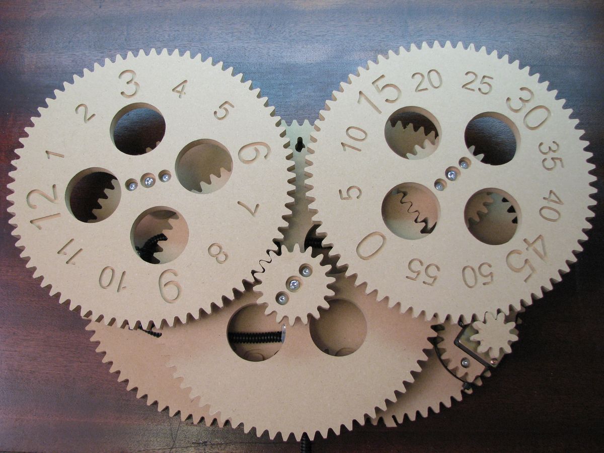
Gears
The gears are made out of MDF. They were painted to have a metallic look however the look I was going for was not achieved. Initially I was thinking of making the gears look like they were made of metal and left to rust for a few dozen years. I found some cool products that would give me that rusted effect but they were a bit too expensive. I settled for a can of Krylon Black Metallic Hammered Finish paint. The sample on the lid is a very nice black with subtle bit of gray. I think this might be from a bad batch since the final look is not as black as it should be. It also made taking pictures of the final clock a bit tough since even with modest lighting the glare was horrible.
The gear arrangement is as follows:
- 9 tooth motor gear
- 72 tooth minute gear with a 24 tooth secondary
- 72 tooth intermediate gear with a 18 tooth secondary
- 72 tooth hour gear
To achieve the correct timing the 9 tooth motor gear is advanced 4 steps every 9 seconds. By moving 4 steps at a time the motor routines can be simple since the motor is always at rest with the same coil energized.
Code
The code is basically split into two sections, there is an iterative loop that monitors the buttons for a change in state and checks if the internal clock has crossed the 9 second mark. If one of those conditions has occurred the stepper motor is driven appropriately.
The other section of code is interrupt driven and it keeps track of time. An interrupt is triggered every 0.1 seconds and adjusts an internal clock as needed. There is a true running clock inside, if you connect the clock PIC pin 6 to a computer serial port operating at 9600 bps you will see the internal clock values update once per second. The clock value in this case is arbitrary since it is never shown and will not be the same as what the gears are displaying but this same code will be used in future projects which will use this code display time.
Schematic

The schematic is just a quick back of the napkin design. I may cad up a proper design in the future. In the mean time if you have any questions about this one please ask.
Click on the image for a large version.
Download Code
If you are interested in burning your own chip you can get the HEX file here. If you would like to have a look at the source code that is available as a free item in the online store.
Download CAD Files

If you have access to a CNC machine you could cut your own clock parts. This zip archive has all of the DXF files for all of the clock parts. The g-code TAP files are also included if you prefer to use them. Please note that these files are only to be used to personal use.
Pictures