
Button Code – Single Button Code Entry System

The Button Code is a system that allows a single button to act as a keypad. The user enters a 4 digit code into the system using button taps. The button can be placed where the public can access it since like a keypad there are many combinations to keep guessers from activation the system. When the correct code is entered a form-C relay is activated (Normally Open and Normally Closed relay contacts). When activated it can either activate for a programmed time or simply toggle the output whenever the correct code is entered.
This simple circuit allow for simple control of things such as:
- Garage Door Openers – Pulse the door open button for a second to operate.
- Lighting – Toggle to turn on, toggle to turn off.
- Door Access – Pulse the door lock for 3 or 4 seconds.
- Simple Security System – Toggle alarm power on or off.
To purchase this controller please have a look at our online store.
If you prefer reading a printed manual have a look at the manual here (pdf).
Video
Overview
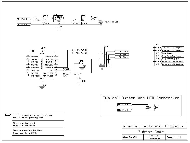
The heart of the button code project is a PIC 16f628A microcontroller (PDF). This microcontroller monitors user input using a single button that is connected to the button terminals. The controller provides visual feedback to the user over the same button terminals, this means that only 2 wires are needed to be run to the button location. A relay is controlled by the system, it is only activated when the correct code has been entered.
Modes
The button code system has two operating modes. One is normal running mode where it is waiting for a code to be entered and reacts as programmed when the correct code is entered. The second running mode is program mode, this mode is used to configure the system to operate is as you desire.
Changing Running Modes
There is a program jumper that is used to change the running mode. When the jumper is out the mode is the normal running mode, when the jumper is in the system is in program mode.
Please note that the state of the jumper is only checked when power is applied. This means that if the system is in program mode and the jumper is removed, the mode will not change until power is removed and re-applied.
Normal Running Mode
In normal running mode the system is waiting for a code to be entered and reacts as programmed when the correct code is entered. To enter a code tap the button once for each number in code digit, wait for a confirmation flash, then proceed with the next digit in the 4 digit sequence.
For example if the code to be entered is 1, 2, 3, 4 you would do the following.
•   Press the button 1 time
•   Wait for a confirmation flash from the LED
•   Press the button 2 times
•   Wait for a confirmation flash from the LED
•   Press the button 3 times
•   Wait for a confirmation flash from the LED
•   Press the button 4 times
After the 4 digit code has been entered the system will operate as programmed. If the code is wrong a slow flash will be displayed on the LED.
Program Mode
There are three program menu options, to change between the menu options press and hold the button for at least 3 seconds. When the button is released you will be in the next menu option. The LED will flash to let you know what menu option you are in. For example Flash, Flash, pause, Flash, Flash, pause… means that the system is in menu 2.
Program Mode Menu Options
1) Code Change: Used to change the 4 digit system code. Tap in the new code that is desired just as you would when in normal running mode. The system will give you a fast flash confirmation when the new code has been saved.
2) Activation Time Change: Used to change the activation time desired. Tap the button once for each second desired. For example if you would like a 10 second activation time just tap the button 10 times. The system will give you a fast flash confirmation when the new activation time has been saved.
3) Operation Mode Change: Used to change the operation style.
- The first mode is a timed mode, in this mode the relay is activated when the correct code is entered and de-activates after the activation time is up.
- The second mode is a toggle mode, in this mode the relay state is changed whenever a correct code has been entered. For example if the relay is de-activated it will activate when a correct code is entered and if the relay is activated when a correct code is entered is will de-activate.
To change the mode, press the button once for the first mode and twice for the second mode.
Code
The system is continuously monitoring the state of the button since that is the only user input. The result of button presses will vary greatly depending on the state of the system. The actual system code, the activation time and the operational mode are stored in non-volatile flash memory so that is remains without power.
Schematic

Click on the image above for a PDF version of the schematic.
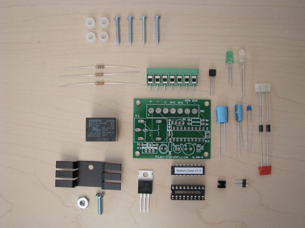
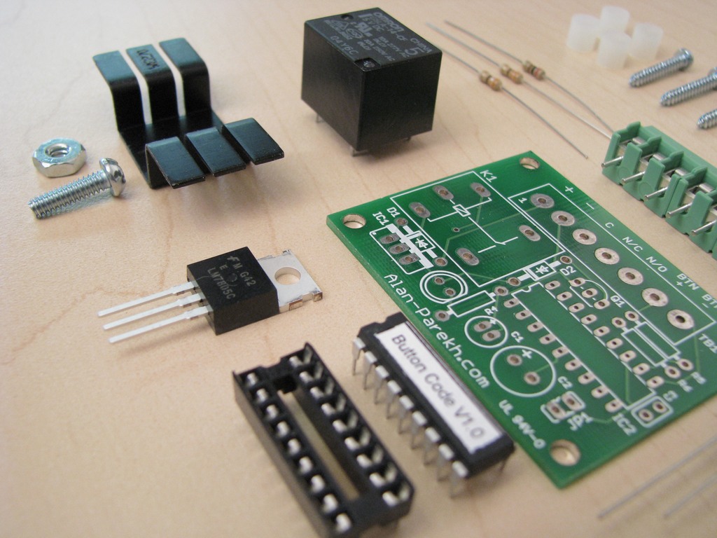
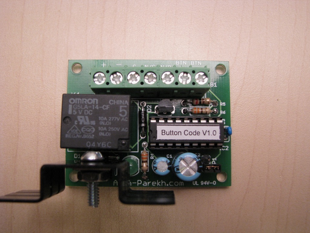
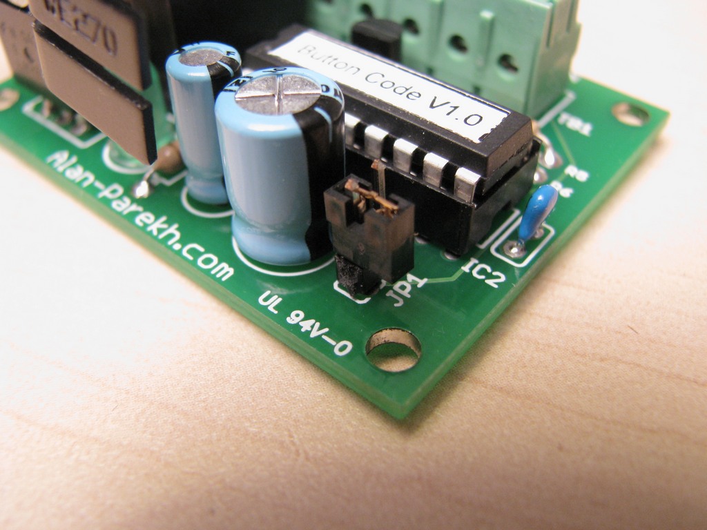
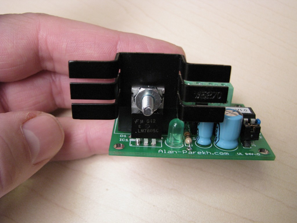
Circuit Board
Below are images of the circuit board. Board width is 53.5mm, height is 41.4mm.
All layers of circuit board.

Silk screen layer.

Top copper layer.

Bottom copper layer.

Download Code
If you are interested in burning your own chip you can get the HEX file here. If you would like to have a look at the source code that is available as a free item in the online store.
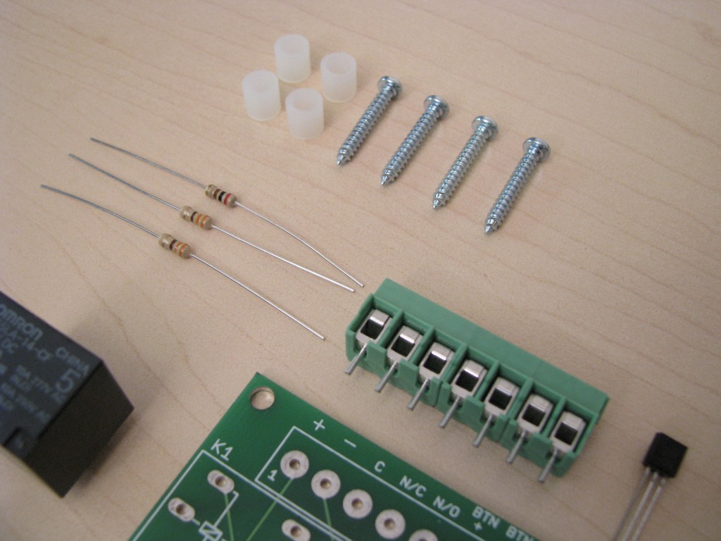
Pictures


on December 8th, 2009 at 4:13 am
[…] Button Code is a system that allows a single button to act as a keypad. The user enters a 4 digit code into the system using button taps. The button can be placed where […]
on December 8th, 2009 at 6:00 am
[…] Button Code is a system that allows a single button to act as a keypad. The user enters a 4 digit code into the system using button taps. The button can be placed wHERE […]
on December 8th, 2009 at 10:17 am
[…] Button Code is a system that allows a single button to act as a keypad. The user enters a 4 digit code into the system using button taps. The button can be placed where […]
on December 9th, 2009 at 3:30 am
[…] Button Code is a system that allows a single button to act as a keypad. The user enters a 4 digit code into the system using button taps. The button can be placed where […]
on December 9th, 2009 at 6:34 am
[…] and a video explaining how the kit works can be found here. Tags: hacked-gadgets, kit, PIC Share this […]
on December 19th, 2009 at 5:50 am
[…] This kit was lots of fun to make and it provides a unique way to enter in a secure code. You can see documentation about it here, if you want to get your own Button Code kit they are available here (if you buy one and also win […]
on January 4th, 2010 at 11:39 pm
Can you detail the hyper terminal part for us? is it a serial connection to the PC and how do I set up HT to read the output? Thanks for the cool controller!
on January 5th, 2010 at 5:16 am
Hi George,
Sorry for not providing the documentation for that. I will add some formal stuff a bit later. For now I hope this comment will get you going.
In Hyper Terminal use the following settings.
Bits per second: 9600
Data Bits: 8
Parity: none
Stop Bits: 1
Flow Control: none
Hardware Connections are as follows.
Pin 1 of PIC microcontroller through 1K resistor to pin 2 of computer serial DB9 (if you are using a DB25 connector go to pin 3)
Ground of Button Code board (terminal block pin 2) to pin 5 of computer serial DB9 (if you are using a DB25 connection go to pin 7)
The Button Code board outputs what some call TTL level RS232 which most computer serial ports can read but some computers have issues with it.
on January 13th, 2010 at 11:28 am
Hi Alan,
Many thanks for a great project, it works a treat.
I would like to run mine from a battery, however the standing current is just a little too high.
Would it be possible to put the PIC into Sleep Mode until the button is pressed ?
RB Interrupt ?
Best wishes
Stewart
on January 13th, 2010 at 11:37 am
Hi Stewart,
Thanks for the feedback. If the relay is not normally energized you may want to look into removing the power on LED. It is drawing the majority of the power when the system doesn’t have the relay energized.
on January 13th, 2010 at 12:12 pm
Hi Alan,
Thanks for your (very) quick response.
I have omitted the LED, and replaced the 78L05 with a HT1050 regulator which has a lower dropout voltage. With the PIC out of the board the current is <10uA, however with the PIC in this rises to about 1mA. This is probably, long term, too much for a PP3 battery.
If I had a copy of PicBasic I would have a go at adding sleep and wake up on interrupt into the code, unfortunately all of my development is done using MikroBasic.
Best wishes
Stewart
on January 13th, 2010 at 12:48 pm
Hi Stewart,
I just had a look at the code. There is a 1 ms pause in the main loop to slow things down a bit. I also tool a look at the nap and sleep functions of PICBasic Pro and the smallest low power time duration is 18 ms.
The switch is not on an interrupt pin either so that is not really an option. I am not sure how well it would work given the dual input/output function that the pins take on in this project.
One solution would be to drop your power to nothing by adding a toggle switch to kill power completely when not in use. This could be located next to the code entry button, worst case scenario a bad guy turns on the switch and draws 1mA until you notice.
I have never played with those batteries but after having a look at the specs they seem to pack quite the punch, with only a 1mA draw I would think they could run for quite some time. It will be the 100mA that the relay draws that will suck the life out of them…
Let us know how you make out!
on January 13th, 2010 at 1:25 pm
Hi Alan,
I was looking at the way the switch was connected. It is on PortB which has the capability of generating an interrupt on change on RB7RB4. Activity on any of those pins should be able to generate a wake up on interrupt activity.
I use this on RF units with small keypad which spend a lot of their time – just sitting idle.
The power required until you press a key is <100uA. It is the long term drain which kills alkaline batteries. I will try with a new PP3 and see how long that lasts.
Thanks for your help. As you say, I can always put a power switch in circuit…
Best regards
Stewart
on January 13th, 2010 at 2:06 pm
Hi Stewart,
Very true, I have never used a pin interrupt on this micro and I was just going by the pin out diagram that has only the B0 interrupt shown. But with a closer look at the data sheet you are correct the pins that it is connected to sure do have pin change interrupt capability on them.
When I revisit the code to add some additional featured I will have to look into that. Thanks for the heads up. 🙂
on January 14th, 2010 at 6:30 am
No problem Alan 🙂
Stewart
on May 11th, 2010 at 5:04 pm
With one simple addition to its brain, this system could be used for utterly stealth front door entry control.
If the system detects a single “dumb” press-release, it could trigger a switch that is wired to the house’s doorbell ringer. Otherwise if it detects the correct code entry, it acts as a door lock release. This way, you can use the existing doorbell switch, not do any extra wiring, and have a completely* stealth code entry system.
* of course the door needs an electrically actuated lock release, so I guess it’s only MOSTLY stealth.
on July 2nd, 2010 at 1:03 pm
[…] This would be hard to implement if you’re working on a watertight package but we like the fact that an unsuspecting house guest won’t go blind if searching for a flashlight during a storm. One last thing, the code entry system is PIC based which reminds us of [Alan Parekh's] one-button system. […]
on August 2nd, 2010 at 12:09 am
[…] single button code lock for a garage door. I got the idea from Alan Parekh’s project (called Button Code) and decided to build by own based around an ATtiny13 microcontroller. Join me after the break for […]
on August 2nd, 2010 at 9:04 am
[…] a combination lock that opens the garage door. The idea isn’t original, it is based on [Alan Parekh's] button code project, but I did develop my own hardware and software. A four digit code is entered by pressing the […]
on August 3rd, 2010 at 6:43 am
[…] is written in Basic. The inspiration for this project came from Alan Parekh’s project (called Button Code). The four digit code is entered using one button. First digit is entered then wait for the led to […]
on August 4th, 2010 at 12:19 am
[…] Many of us know Mike from his work at Hack a Day. I am honored that this design was inspired by my Button Code project! The project is based around a ATtiny13 microcontroller just because that is what he had laying […]
on October 15th, 2010 at 8:51 am
[…] Code – Single Button Code Entry System – [Link] Tags: button, Code Filed in Control | 1 views No Comments […]
on July 14th, 2011 at 3:57 am
I can’t find the transistor 2N4401 in my country,, can I replace with an other one?
What I found here:
2N2222 “NPN”
2N2905 “PNP”
2N2907 “PNP”
2N3773 “NPN”
2N3904 “NPN”
2N3906 “PNP” .
2N4391 “N-Channel JFET Switch Transistor”
2N4403 “PNP”
2N4871 “Unijunction”
2N5401 “PNP”
2N5551 “NPN”
Ohhh,,
Is your transistor NPN or PNP?
on July 14th, 2011 at 4:00 am
Also I got a question Mr.Alan Parekh
You didn’t write to the diodes type ,,
Thanks for your help
on July 14th, 2011 at 2:11 pm
Hi Amr,
The transistor is a generic NPN. Use the 2N2222 or the 2N3904, they are generic and will work fine.
Alan
on July 14th, 2011 at 2:13 pm
This is the diode that is used (or anything similar).
http://alan-parekh.vstore.ca/1a-diode-p-68.html
on September 9th, 2011 at 4:16 pm
Do you know how to converte this circuit to work with keypad?
on September 9th, 2011 at 4:19 pm
Hi Amr,
There is really no way since it was not designed to interface with a full keypad.
on September 27th, 2011 at 8:19 am
Alan
This simple little encoder works like a charm.
Well done
on January 20th, 2012 at 8:09 am
This project is nice as an end project at the tech college. But no one singel Chinees will adopt it as apruduct in order to MAKE MONEY. The process of entering the code is long. Old people will forget while entering which digit they are at 🙂 it going back from Windows to MS-Dos at key pad you remember the number just have to push here need to remeber the number -remember which digit you are at-and take care on timing9again old people problem).
I would Alan you are skilled guy move on to your next project !
on February 28th, 2012 at 6:15 am
Hi Mr.Alan Parekh,,
Can You change the way to change the code by asking for the last code first , then the system can change the code
on February 28th, 2012 at 11:19 am
Hi Amr,
Yes, that could be done, the code is available and it would be a change you would need to make though. Only issue I can think of is if you forget the code the device would be useless unless you re-program the controller.
on February 28th, 2012 at 5:46 pm
O.K That’s Very Nice,,Can you Send to the hex file for that modification,,Please or tell me how to do this ,,
Thanks alot Mr.Alan Parekh
on February 28th, 2012 at 6:33 pm
Hi Amr,
You can find the source code here.
http://alan-parekh.vstore.ca/product_info.php/cPath/3/products_id/92
on February 28th, 2012 at 9:19 pm
It’s the same one is no diffrent?
on February 28th, 2012 at 9:20 pm
you gave me the same link for the last hex file..what is the different should I have to do?
on February 28th, 2012 at 10:10 pm
Hi Amr,
You will need to edit the code to suit your needs. The link will let you get the original code which you can use as a starting point.
on February 29th, 2012 at 6:56 pm
I’ve got no idea to modify like the file if you can learn me how to do that or tell me what is the line at asm file to modify ,,I’ll be very thankful..
on February 29th, 2012 at 7:47 pm
Hi Amr,
Unfortunately it isn’t as simple as changing one line of code, you will need to write some new code for your custom idea. I am sorry to say that at this time we would not be able to customize the code for your application. You can contact any Microchip contract firmware developer to help you with this though.
on December 4th, 2012 at 11:03 am
Hi Alan.
Great design.
I would like to change the 4 digit to 2 digits.
After this change, how can I recompile the code?
Even with the original code, I could not compile in MPLAB + PBP.
What is wrong?
on December 4th, 2012 at 11:21 pm
Hi Hélio,
Thanks. I am using PBP pro. I am not sure why it doesn’t assemble for you. Is there an error message that you get?
on December 5th, 2012 at 8:59 am
After several tests, I found the problem.
I compiled now with Micro Code Studio.
With the MPASM assembler did not work, so I try with the PE assembler (built-in MCS) and work fine.
Congratulations for the work. Thank you.
on November 18th, 2013 at 10:13 pm
How can I change the program to make it usable for a attiny13 microchip
on November 20th, 2013 at 4:18 am
Hi Chris,
You would need to write a new program for the attiny.
on November 21st, 2013 at 3:34 pm
I have tried the on on jumptuck but it is missing header files and I can not find them so how could I go about
writing a new program for this