Fish Tank Lights and Temperature Sensor
The left Picture shows the lights in blue mode, the right one shows the current tank water temperature. There are 6 modes in total 4 solid color modes (Blue, Red, Green, White) and 2 “cycle” modes. The cycle modes allow the lights to do a slow transition from one color to the next.
Why
When the tank is cleaned the fish are removed and placed in a small amount of the tank water. The problem is that fish don’t like rapid temperature fluctuations. I guess a simple in tank or stick on thermometer would have done the trick but what is the fun in that? If the unit just did temperature monitoring it would have been such a waste of processor capability, so I thought adding colored lighting would be a great addition.
OVERVIEW
- Uses 16 high power LED’s, 4 red, 4 green, 4 white and 4 blue.
- The tube that the LEDs are mounted in is a section of 3/4 inch PVC conduit.
- LCD Display to display the mode the unit is in and show the temperature.
- Liquid sealed temperature to read the water temperature.
- One button to change between modes.
- Photocell to turn off the lights when there is adequate room light. This is wired and calibrated but this function has been remove to allow the lights to remain on all the time.
Be informed when new projects are available or additional project information is posted by signing up to our mailing list.
STEPS TO CONSTRUCT FISH TANK LIGHTS
1) Prep the Light Tube: Cut a section of the PVC Conduit to the desired length, a hacksaw makes quick work of this type of pipe. Cut the pipe in half length wise, drill 16 evenly spaced holes in one of the halves.
2) Mount and Wire LED’s: Hot glue an LED into each of the holes alternating the colors. After the glue is dry, wire up the like colored LED’s in series with an adequate current limiting resistor.
3) Wire the Temperature Sensor: Connect the 3 terminal temperature sensor up to the cable that will be used. Hot glue and heat shrink will make for a water tight seal. The temperature sensor being used is made by Dallas Semiconductor, it is model DS1822.
4) Assemble the Light Tube: Connect the LED power connections to the cable that will be used. Lay the temperature sensor cable through the light tube leaving enough sticking out the side to dip into the water from the height the unit will be mounted. Wrap the entire light tube in black electrical tape, making sure the LED’s are not covered.
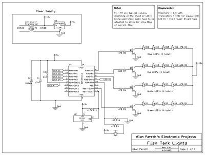
5) Construct Circuit Board: Use some perf board to create the circuit board, there is schematic below to aid in the construction of the circuit. Wire it up to a 2 line LCD panel.
6) Connect External Cables to Control Unit: To power this unit I used an 18VDC wall wart type power supply. A 5V regulator was used to provide stable and clean power the PIC. Hook up the temperature sensor wires LED power cable to the perf board.
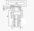
7) Wire up the LCD to the Control Unit: See the schematic below for the pin to pin connections. This was adapted from an old version of PIC microcontroller, all of the non 16f628 connections have been cleaned up.
8) Mount Switch and LCD: Find an adequate project box to house the guts. Hopefully yours will look better than my old 5 ¼ floppy drive storage case. I was going to use a slick clear plastic project box and spray the inside black (after masking off the LCD area). Well the spray paint I bought started to eat the plastic 🙁 Drill and mount the switch on the case with leads long enough to tie into perf board. Cut a hole in the case and mount the LCD, hot glue is my friend in this case.
9) Program the PIC: Download the PIC microcontroller code and burn it onto the chip using a programmer.
10) Stuff Project Box: Jam the perf board into the project box and close it with something better than the tie strap that I am using 🙂
11) Entertain you Fish: Turn on the system and amaze your fish with the nice color combinations!
SCHEMATIC DIAGRAMS
|
Click on an image for a printable size. The PIC pins marked as LCD are shown on the 2nd diagram in relation to the LCD display. To get additional information about the PIC 16f628 microcontroller go here. Check out the links for places to buy cheap components! |
DOWNLOAD CODE & BURN METHOD
Here is the HEX file that can be burnt directly to a PIC 16f628 microcontroller. It needs to be burnt to the chip using a programmer. Programmers can be constructed very easily. I initially constructed a no parts programmer to program 16c84 chips but later converted it to program 16c628 chips. There are now much better programmer that can be built or purchased inexpensively. There are some very good free chip burning programs available, Win PIC and FPP are the ones that I use. If you want the source code it is available free of charge from the online store.
FISH TANK LIGHTS PICTURES
Front view of tank, the lighting bar is not visible since it is nicely hidden behind the plastic band that runs around the top of the tank.
Side view of tank.
Top view of tank and light pipe.
The controller, button to change modes is on the bottom right, photocell is in the upper right area, LCD displays the tank temperature and the light mode.
Mode here is solid white.
Board on the right is the perf board containing the circuit, the LCD is mounted on the case (on the left).
Temperature cable on the right, 4 green LEDs are on.
Close up of the temperature sensor, since the electrical connections were hot glued and then heat shrinked it provides a water tight connection and can be left in the water.
Green mode. I guess i am advertising for 7-11, didn’t realize the slurpee cup was back there 🙂
Red mode.
Top view of tank with light pipe on the right.
These super bright LEDs are actually blinding when you look at them directly!
There are actually 4 green LEDs but since the angles that they are installed they look like they have different intensities.
This is the temperature sensor that is connected to the end of the light pipe, it is long enough to be submerged fully into the tank.
Side view of the light pipe.
LED power and the temperature cable enters on this end. The temperature cable just runs the length of the pipe and comes out the other end. I hot glued the connection to prevent any strain on the connections inside the pipe.
A few steel clips are used to anchor the unit, flat steel painted black would look much better though.
Close up of the LEDs every 4th one is the same color.
Red Mode.
White Mode.
With the flash on it is hard to see the color of the light, the pipe is hidden behind the black plastic tank trim.
23.0 deg C, the mode is cycle fast, this mode cycles through all of the LED colors quickly.
23.625 deg C, the mode is cycle slow, this mode cycles through all of the LED colors slowly.
Back of project box (old 5 1/4 inch floppy case). This needs a better box, this one is very sad looking 🙁
Inside Case
Shows the LCD connector at the top of the picture.
A few dabs of hot glue hold in the LCD, this way it is somewhat removable.Got to love the way hot glue can make a project easy to assemble 🙂
Top of picture shows the photocell entry. It isn’t programmed in the HEX code that is provided so this can be disregarded. I found that I liked the lights on 24 hours a day, and not just when it was dark.
The circuit board is at the right of the picture, lots of wires for a small project!


