
Multimeter Clock – Simpson 260

Get your own Multimeter Clock Kit here.
This project was lots of fun to build, thanks to Design News for featuring the project in the magazine. The Design News photo shoot was lots of fun, you can see one of the outtake pictures in this Hacked Gadgets article.
Overview
The Multimeter Clock consists of three multimeters, the first meter displays hours, the second displays minutes and the last displays seconds. A 16F628A PIC microcontroller keeps track of time and outputs a calculated current to each meter to display the current time.
How It Works
The user enters the time by pressing three time adjust buttons. The first button increments the hours, the second button increments the minutes and the third button resets the seconds. Once the time has been entered the microcontroller will keep track of time from there. An interrupt fires every 10th of a second to increment a 10th second counter. Another routine checks to see if we have at least one full second of time, if we do the current time is incremented by a second.
The microcontroller has a separate output for each of the three meters. The meters are all in 0.5 DCmA mode, the negative lead of each meter is grounded and the positive leads are connected to a microcontroller output via a current limiting resistor. The resistor in this case is a 4.7K however this can be adjusted depending on the meter current scale available. Keep in mind that the PIC can deliver a maximum of 25mA to each meter so a meter with a lowest setting above 25mA would not work without additional circuitry. You also want to make sure that you can easily drive the meter to full scale, if the meter is not very accurate it could take 10 or 20% more than the stated current to drive it to full scale. See the table 1 below for a few suggested resistor values.
| Meter Scale | Resistor to Use |
| 0.5mA | 4.7K ohm |
| 1mA | 2.4K ohm |
| 5mA | 510 ohm |
| 10mA | 240 ohm |
Table 1
The controller uses PWM (pulse width modulation) to pulse the current to the 3 meters which allows for precise needle position. For example if the minute meter needs to display 30 then the PWM would be half of the pulses needed to show full scale. When the system is initially started the PWM value is 50% so that the meters aren’t damaged by being accidentally overdriven. Originally the current limiting resistors were going to be a resistor and a calibration pot so that the full scale current to be adjusted by turning a pot. To get rid of the requirement of 3 calibration pots a scale adjustment mode was created. This allows the user to set the PWM value needed to bring each of the 3 meters to full scale. This value is then stored to non-volatile memory so that it never needs to be touched again.
Since the meter displaying the seconds is being updated every second there was a tendency for it to bounce from one value to the next. Just like there are watches with ticking second hands and smooth second hands I also wanted this clock design to emulate either mode. If the Smooth second jumper is in the 10th of a second values are introduced into the calculation of the PWM value of the second hand which results in a very smooth moving second hand.
The meter was designed to be plugged in to AC power using a wall adapter but I wanted a way for the time to be maintained in the event of a power outage. The system needs to know when the clock is running on backup power so that it can reduce the amount of power that is being used. This is done with the controllers Main Power Monitor pin. If this pin is grounded the system knows that it’s on battery backup and will drop power to the 3 meters and the hear beat LED.
To implement the battery backup and main power loss monitoring 4 diodes and a resistor were used. D2 is used to raise the regulated power output to around 5.7 volts, D4 is used to feed a 5 volt signal to the Main Power Monitor line when the system is operating from main power. If the main power is lost R5 pulls the Main Power Monitor to ground. Component D3 is used to feed the main 5 volt power that the circuit runs from. The 4.5 volt battery backup power is connected to the 5 volt circuit via D5. The 4.5 volts is fed from 3 AA batteries. The battery pack didn’t come in before the project was complete but it will be the typical plastic battery holder that accepts 3 AA batteries and has two leads coming out. These leads will simply be tied into terminal block TB2.
How to Use the Multimeter Clock
When the clock is first powered up the PWM outputs will default to about 50% of max output. You will first need to adjust the scale of all three meters. This is done by inserting the jumper across the scale adjust pin header. In this mode only the meter being adjusted will be powered.
- The first button (also used to advance the hours when in clock mode) is used to select which meter is to be adjusted.
- The second button (also used to advance the minutes when in clock mode) is used to decrease the full scale setting of the powered meter.
- The third button (also used to reset the seconds when in clock mode) is used to increase the full scale setting of the powered meter.
The goal here is to move all three meters to exactly full scale. When complete remove the scale adjust jumper to return to normal clock mode, at this time the settings will be saved to non-volatile memory.
The time will also need to be set. The time is adjusted using the three buttons.
- The hour button increments the current time by one hour.
- The minute button increments the current time by one minute.
- The second button resets the seconds.
Building the Clock Circuit
Since the clock controller is built onto a perf board you have lots of flexibility on layout. Construct the circuit according to the schematic diagram. The PIC Microcontroller will need to be programmed with the Multimeter Clock firmware using a PIC chip programmer. When powered up the blue LED will give you a visual indication that things are working, during the power up phase the LED will light steady and as soon as the clock is running it will flash on for one second and off for one second.
The firmware was written in PICBasic Pro so you will need that language if you wish to make changes to the existing functionality. There is still about 20% of the 2K PIC code space still available so there is lots of space for some hacking.
The meter faces of the multimeters will need to be updated to show time scales. I used a program called MeterBasic by Tonne Software. To make a new meter face all you need to do is enter the measurements of the meter face, the name for the meter and scale information. In the end you have a perfect matching scale for your meter. You can download the Hour, Minute and Second faces that I created for this clock here.
As far as the actual multimeter clock housing goes it can be anything you wish. In my case I designed a CAD version of a Simpson 260 multimeter and cut it out on a CNC machine. Why the Simpson 260? Well that was the first analog meter I used in college.
Parts List
| Component | Type | Quantity |
| PIC Microcontroller | Pre-programmed 16F628 chip. | 1 |
| Chip Socket | 18 pin | 1 |
| Circuit Board | 2X3 inch perfboard | 1 |
| Terminal Block | 2 positions | 5 |
| Diode | 1N4401 | 5 |
| 12V Filter Capacitor | 100uF | 1 |
| 5V Filter Capacitor | 47uF | 1 |
| 5V Decouple Capacitor | .01uF | 1 |
| Crystal Oscillator Capacitor | 22 pF | 2 |
| 5V Regulator | LM7805 | 1 |
| Crystal Oscillator | 20 mHz | 1 |
| 4.7K Ohm Resistor | 1/4W | 4 |
| 1K Ohm Resistors | 1/4W | 1 |
| Button | Tactile | 3 |
| Pin Header | 0.1 inch pin header (2 position) | 2 |
| Shorting Jumper | 0.1 inch shorting jumper | 2 |
| Indicator LED | Blue LED | 1 |
| Power Supply | 9 to 12 Volts DC | 1 |
| Multimeters | Analog type, preferably with a 0.5mA setting | 3 |
| 2.4K Ohm Resistor | *Â Â Â Â 1/4W | 3 |
| 510 Ohm Resistor | *Â Â Â Â 1/4W | 3 |
| 240 Ohm Resistor | *Â Â Â Â 1/4W | 3 |
| AA Battery Holder | **Â Â 4.5 Volt | 1 |
* One of these resistor values will be needed if you select a meter without a 0.5mA setting, see Table 1 for resistor suggestions.
** This battery holder is only needed for battery backup.
Video
Download Code
If you are interested in burning your own chip you can get the HEX file here. If you would like to have a look at the source code that is available as a free item in the online store.
Schematic

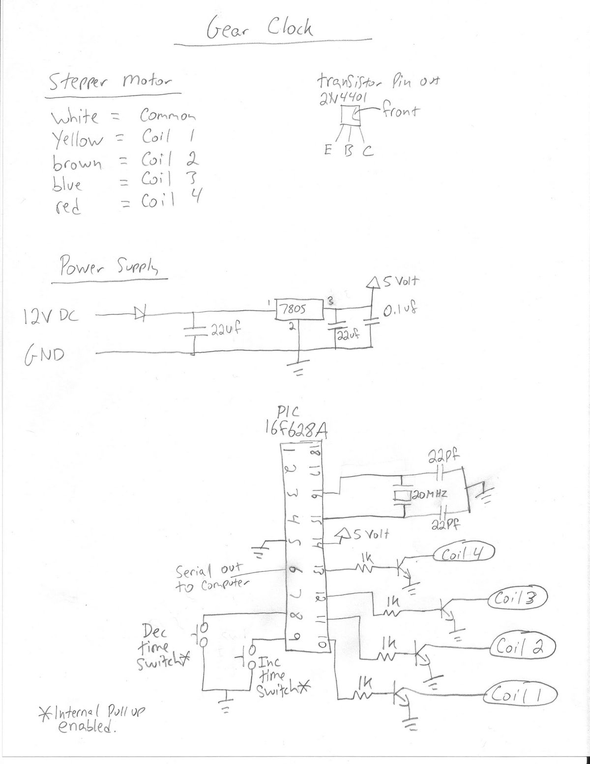
Click on the image for a large version.
Download CAD Files

If you have access to a CNC machine you could cut your own meter clock. There are basically 4 types of pieces, the main face, the panel that goes directly behind the meters, the center spacers and the last spacer which also has a tear drop hanging cutout. This zip archive has all of the DXF files for all of the meter clock parts. Please note that these files are for personal use only.
Building the Simpson 260 Multimeter Housing
The case was created using multiple layers of 1/2 inch MDF. There’s a front piece that has the actual Simpson 260 multimeter details v-carved into it. This is followed by 4 center spacer pieces and finally a back piece that has the hanging teardrop cutout.
The front piece was primed and painted black before getting the details routed into it. All the other pieces were just routed in the CNC machine from raw MDF. I could have saved lots of wood if I built the sections from two pieces since the large center space in my design is wasted space but I decided to do it this way so that there will be no joints in the spacer pieces.
The black painted surface of the meter face was covered with contact paper then the details which will eventually be white were v-carved through the contact paper into the MDF. This provides a way of easily painting the fine white details using a spray gun.


The front face didn’t turn out good, I think it was because of a bad batch of contact paper which left some sticky residue behind that couldn’t be cleaned off without damaging the paint. After spending so much time on the face it was sad to have to scrap it.


For the second attempt I used a new roll of contact paper and thankfully it pulled away from the surface without leaving anything behind.

Assembly of case was quite simple, the 6 pieces were glued using wood glue, then they were screwed together using 6 countersunk wood screws though the machined holes. This way the parts wanted to naturally align themselves. You can see in the pictures that the insert that goes behind the meters needed to be re-worked. It was initially designed with symmetrical mounting tabs but the holes that the meter wires passed though would interfere with the tabs, the new design has the lower tabs moved to make room for the wires. Finally a bit of sanding and painting finished off the look.


Three inexpensive Chinese made meters were used primarily due to their cost. Once opened you can really see why they are so cheap. They function adequately but if I were to do it again I would have spend a bit more money on the meters. You can see the new printed meter faces which were designed with MeterBasic by Tonne Software, cut to size and stuck in place with a bit of tape. Meter face designs can be found here.


Here is what the clock box looked like after the paint was dry just before the electronics were installed. The deep V-carving of the clock name and the word Simpson turned out looking great.


The electronics were installed on a 2X3 inch perfboard. I made a quick paper legend for the terminal block location and button placement selected. A few plastic standoffs were used to hold the circuit board away from the back of the clock by a 1/4 inch.


The panel that makes up the back of the meter bays is spaced by a few washers to add a bit more depth. You can see that the initial idea to hold the meters in place was velcro stuck on using double sided tape but the velcro allowed the meters to move around and sag so that was removed. These meters don’t have much guts on the inside so making a few holes in the rear of the meters to hold them in place with a screw was a much better solution.
Wiring up the clock was simple since there are not many connections. A few bumpers were added to the 4 rear corners so that when it is mounted to a screw on the wall the clock doesn’t scratch the wall.


All done! Here are some final shots of what the end result looks like.


on July 22nd, 2010 at 7:36 am
[…] The full project page is now complete. The kit is also now […]
on July 22nd, 2010 at 7:54 am
[…] the Multimeter Clock article last month? I just got the full build log up. Lots of people wanted the CNC files so that they could cut their own clock, these DXF files are […]
on July 24th, 2010 at 4:38 pm
I like it really much 🙂
on September 4th, 2010 at 7:37 am
[…] all know I have a thing for meter clocks. Instructables user Doug Paradis built this one around the MSP430 microcontroller platform, check […]
on November 15th, 2010 at 5:46 pm
[…] multimeter clock. […]
on March 10th, 2011 at 1:01 pm
I got the “kit”. Just a bag of parts and a perfboard. No instructions. No schematic. Not exactly what I expected.
I’ll attempt to build from the “schematic” on the website, but think it’s going to be a pain in the butt to do so. I’ve built a lot of kits and some stuff from schematic, but this one looks kinda vague… as if the guy who drew it was way to familiar with his project. I am not an EE.
Sigh.
A photo of the wiring side of the perfboard would be way helpful.
on March 10th, 2011 at 11:01 pm
Hi Paul,
Thanks for purchasing the kit and sorry to hear it was not what you expected. I will guide you through any questions you may have. Everything is on the schematic, I am not sure the vague parts you are referring to but all you need to do is connect the pins shown on the schematic.
We have other kits that have very detailed manuals that guide you step by step but the reason this one is listed as advanced is that there is no guidance other than the schematic.
http://alan-parekh.com/kits/
on February 3rd, 2012 at 10:15 am
Hi Alan,
great project! We tried to create a new hex file from your sources. After downloading the file, we could calibrate the multimeters but the normal time software didn’t start to run. Any ideas? Do we have to set some more fuses for the interrupt? We are no experts in PIC programming. Any comments are welcome.
on February 3rd, 2012 at 4:24 pm
Hi Wolfgang,
I am not sure what the problem could be since I have never had this issue. The only thing I can think would be that the scale adjust jumper is not allowing the pin to pull high (internal pull up). Please make sure there is nothing on this pin that causes it to always be pulled down.
on March 21st, 2012 at 5:32 pm
Hi alan,
I was looking at the schematic and have a few questions. Concerning c3 and c4, do they make a connection to pin 1 and pin 3 respectively.. Also do all the grounds share one ground? I am assuming so but wanted to check. Also i am looking for the controller.. Do you still have them for sale and if so how much? Thank you for your time.
on March 21st, 2012 at 8:26 pm
Hi Andy,
Yes all intersecting lines are connections, sorry for the confusion.
The first link in the article (just under the main picture) will take you to the kit link. Sorry, this chip is not currently available as a separate per-programmed chip but if you have a programmer you can download the code and burn one.
on November 3rd, 2014 at 1:33 am
I want to see if I can buy completed clock ?
I also want to see if it can have Timer function?
Actually I just need Timer function for 60 min
I even don’t need a clock function
Please let me know