
Gear Clock

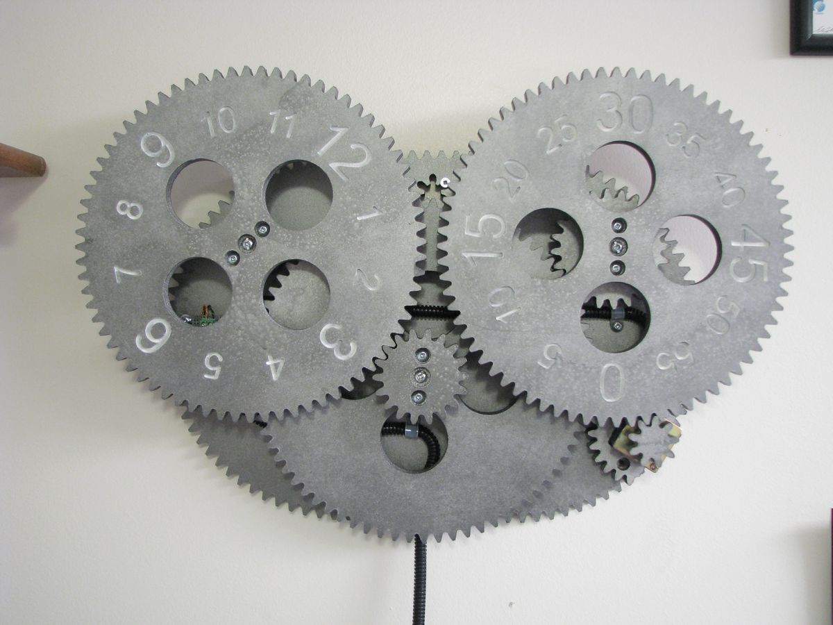
Ever since I setup the CNC machine and built the controller housing I have been playing around with various ideas. Wooden gear projects have been around for a long time, and lots of people have made conventional gear clocks. I wanted to do something a bit different. This project combines some electronics and lots of wood.
Big thanks to The MAD Museum (Mechanical Art and Design Museum) for wanting to add the first production gear clock to their collection of items on display. They have a huge collection of other quirky mechanical machines, marble machines etc. You can visit it on display if you ever find yourself in Stratford upon Avon, UK.
**UPDATE** This project is now available as a kit. Please have a look at the Gear Clock Kit page in the online store or have a look at the Gear Clock Kit assembly page for additional assembly information.
The information below is of the prototype version, the CAD DXF and PIC Microcontroller HEX files of the kit version are available here on the kit page. If you are building one I recommend that you make the kit version.
Video
Overview
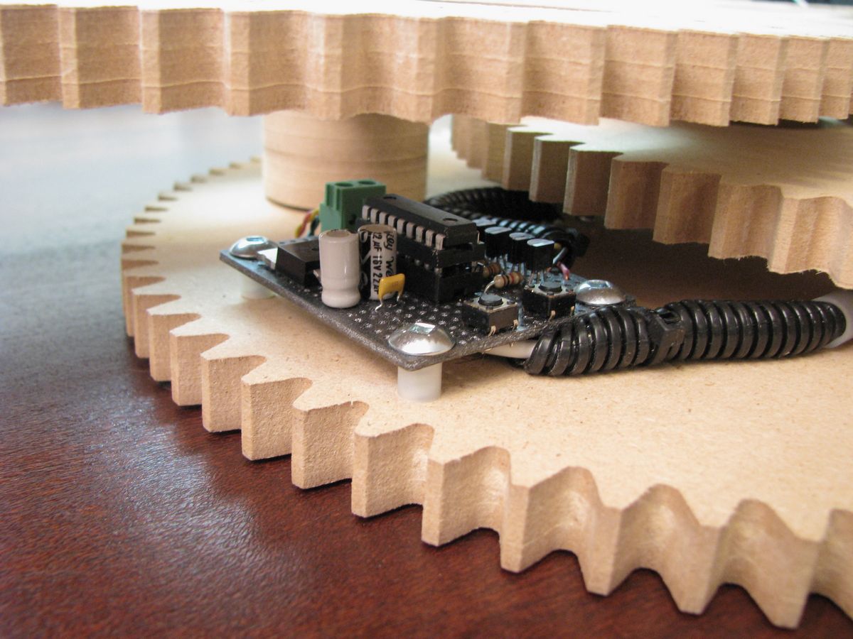
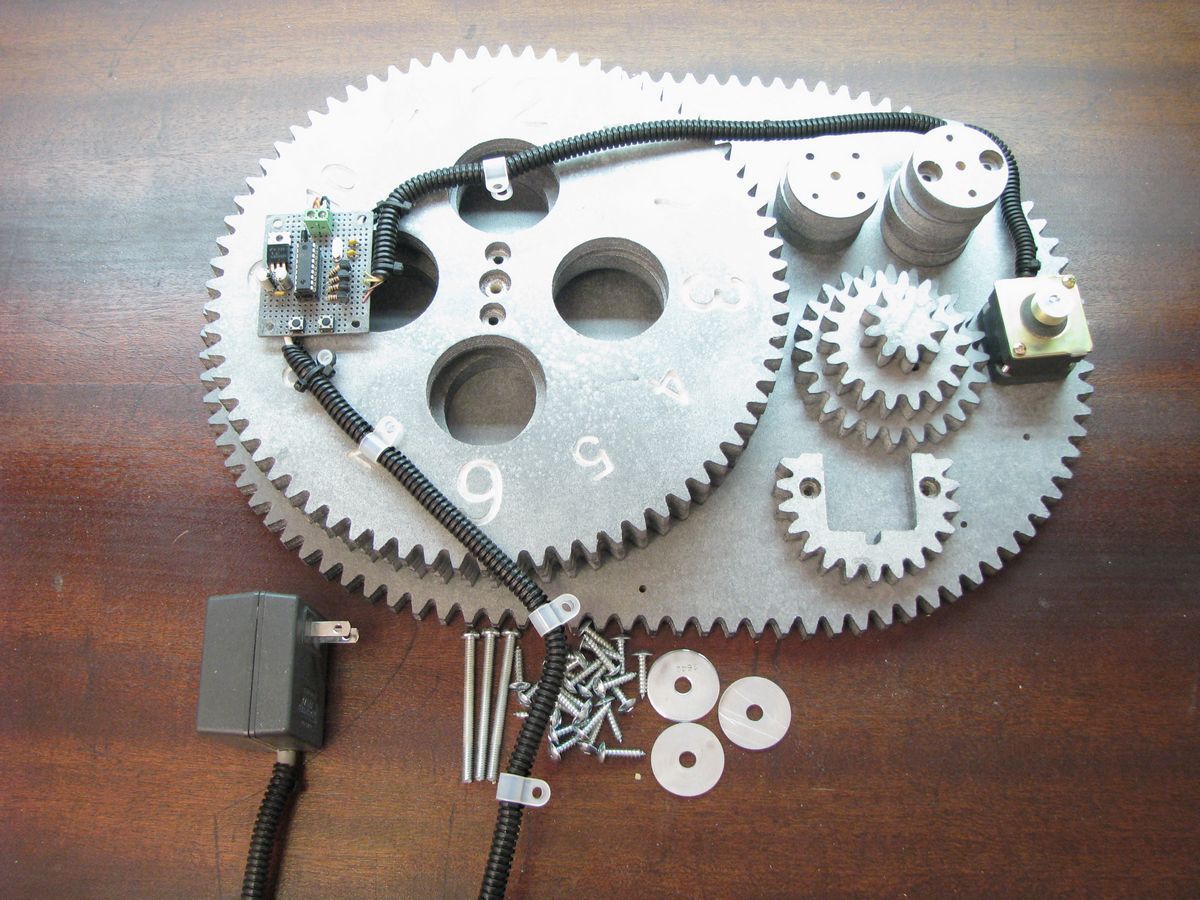
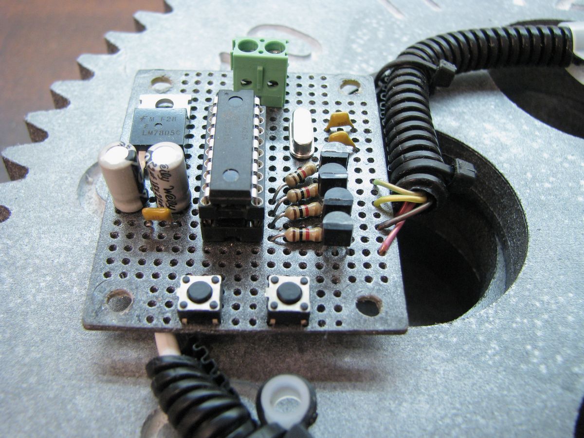
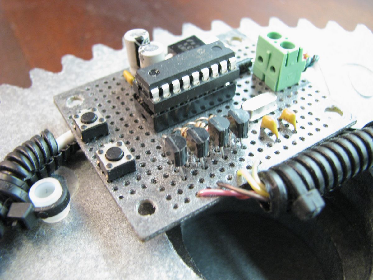
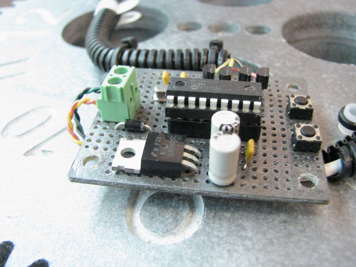
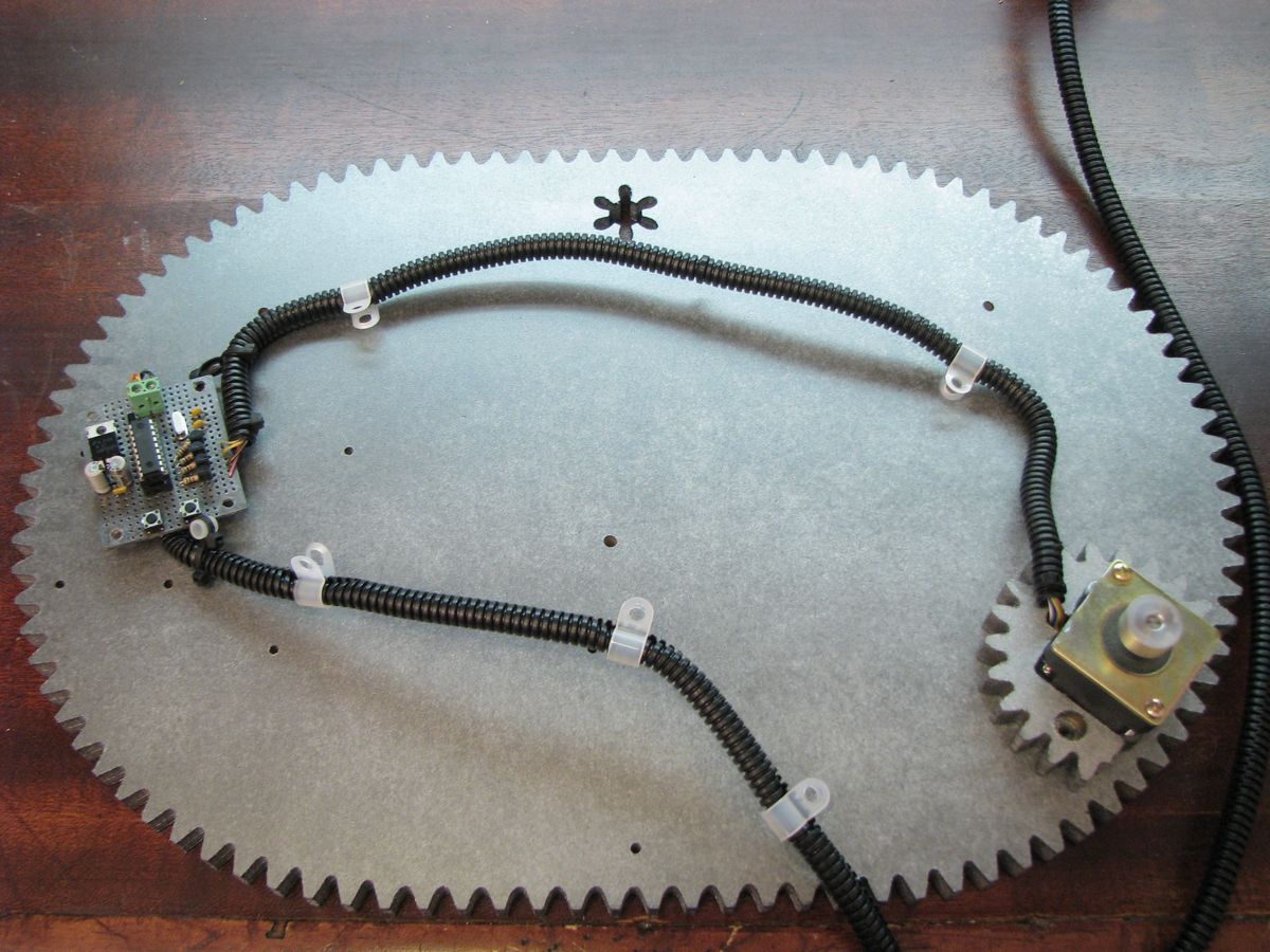
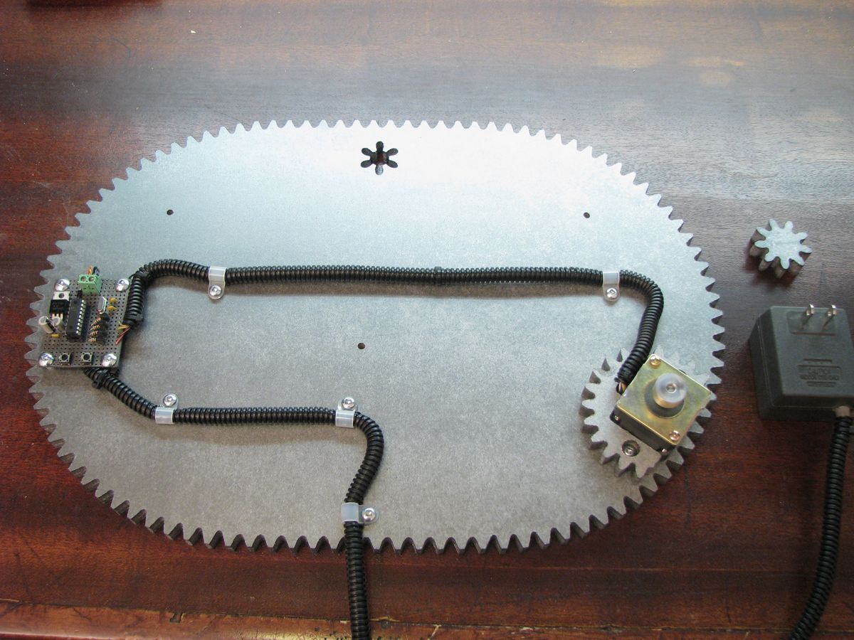
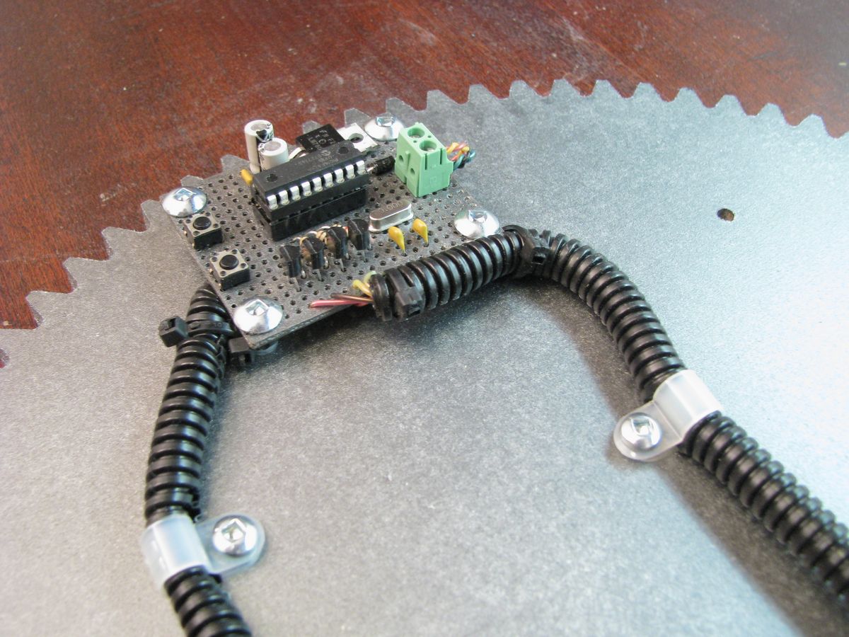
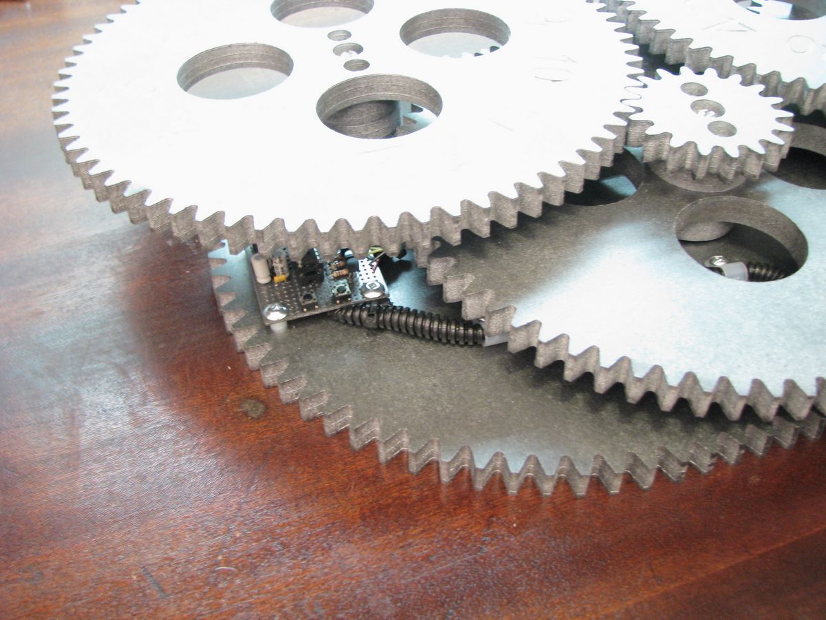
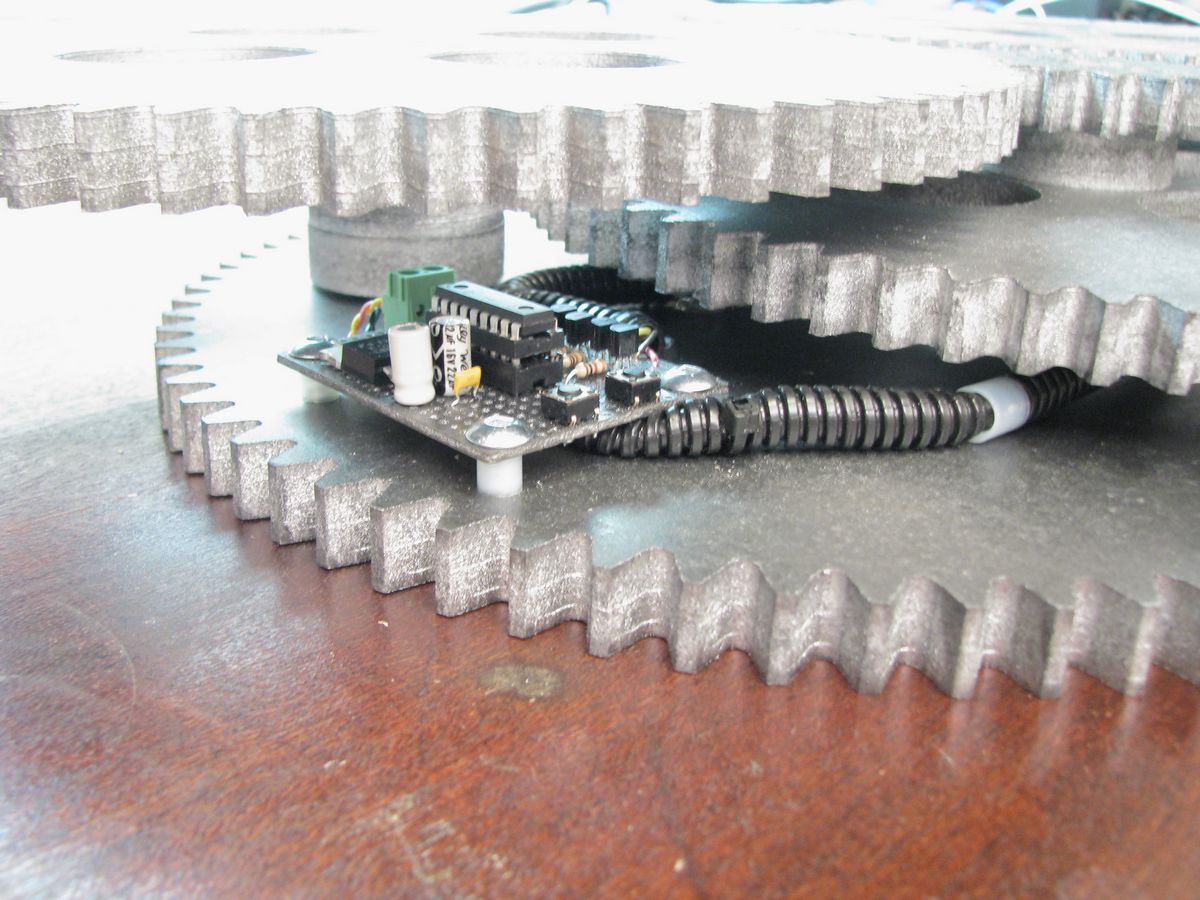
The heart of the clock is a PIC 16f628A microcontroller (PDF). This microcontroller has an internal oscillator however an external 20MHz crystal oscillator is being used since it will have to accurately keep track of time for weeks and months. The microcontroller is interfaced to two buttons and one motor.
Buttons
The interface is very simple, it consists of two buttons. When the left button is pressed the clock advances time using the motor. When the right button is pressed the clock decrements time using the motor. The only issue is when you need to correct time by many hours you would have to keep the button pressed for a long time. The stepper motor is also always energized to prevent the gears from slipping. To overcome this issue when both buttons are pressed the stepper motor is deenergized and the minute gear can be spun freely.
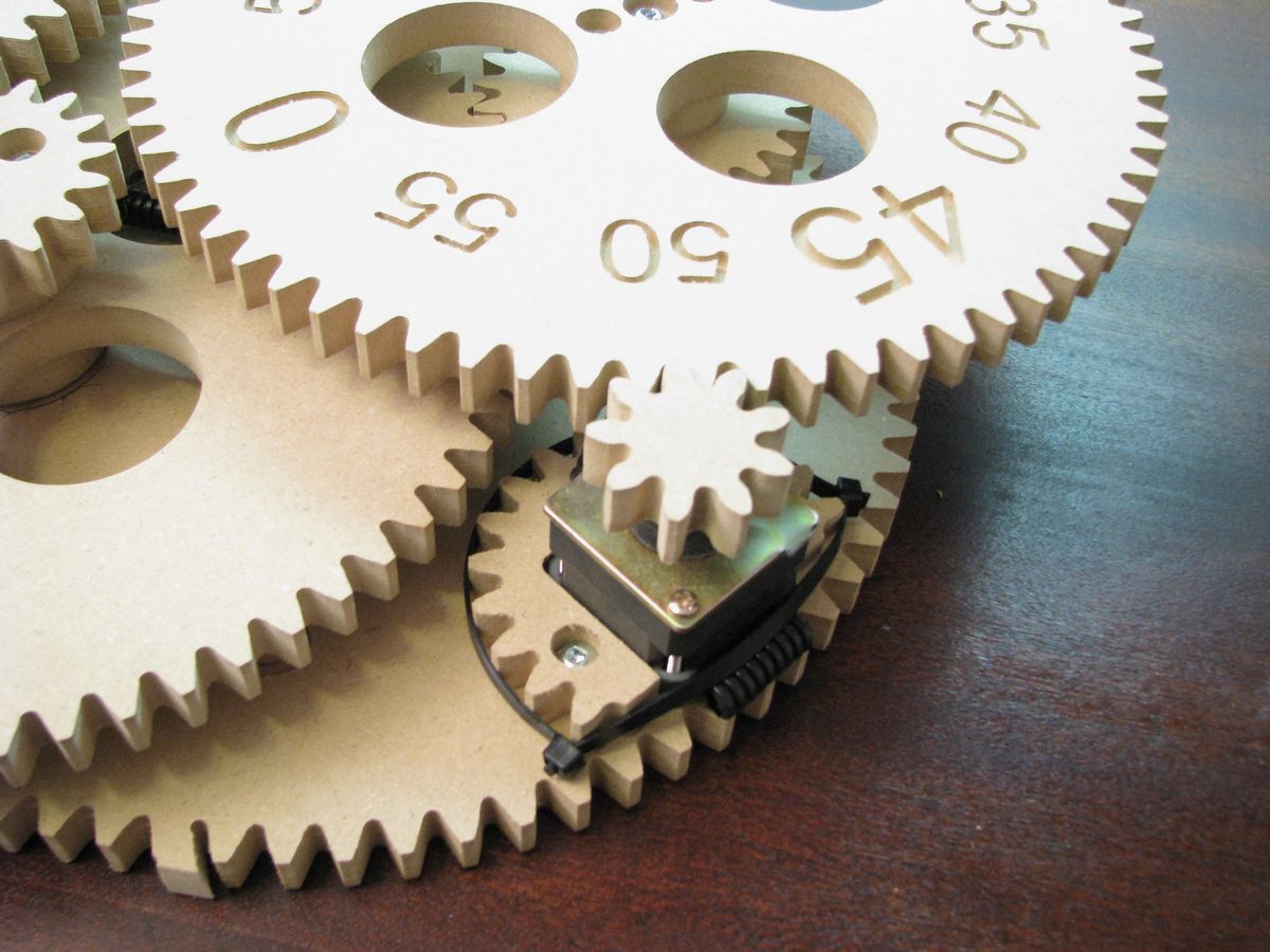
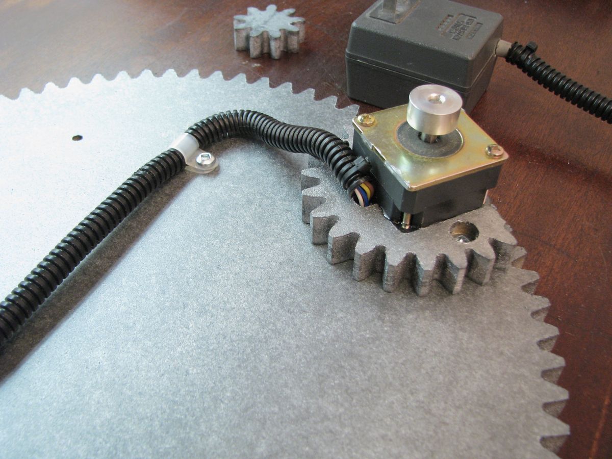
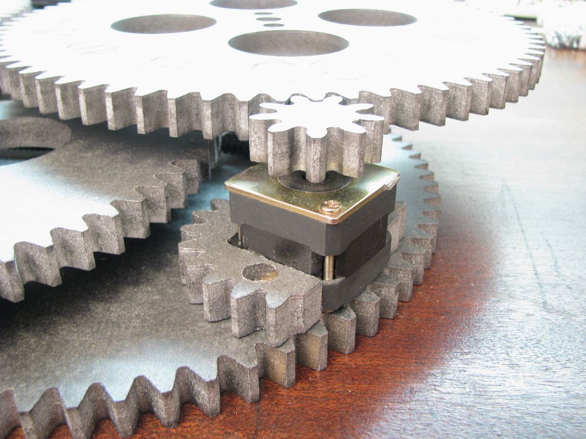
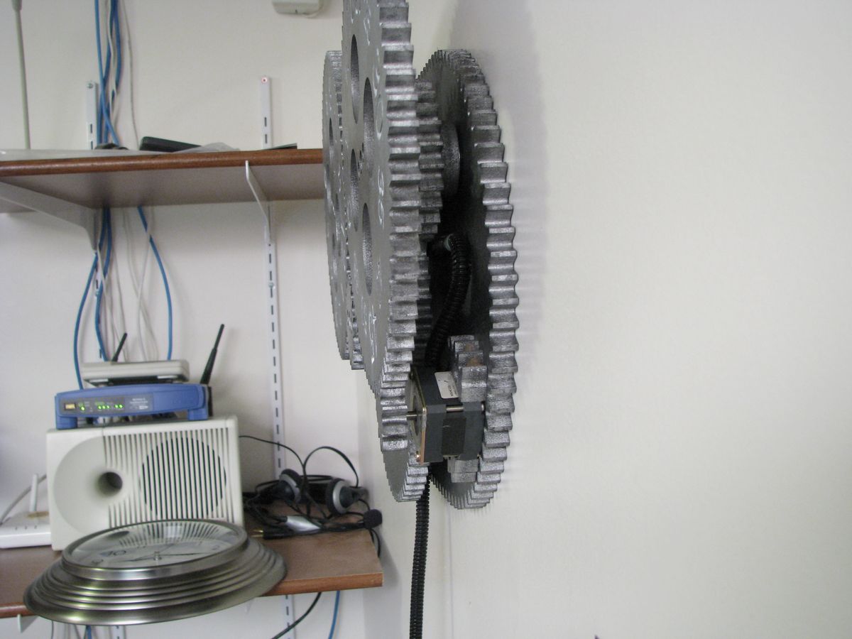
Motor
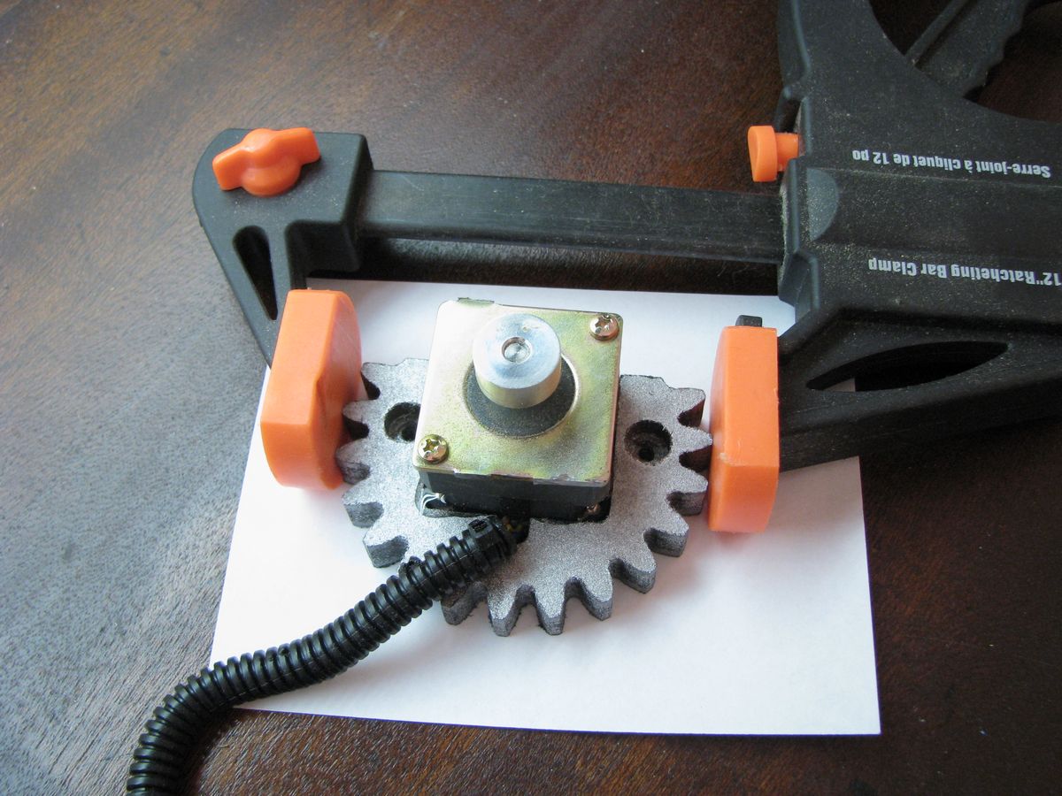
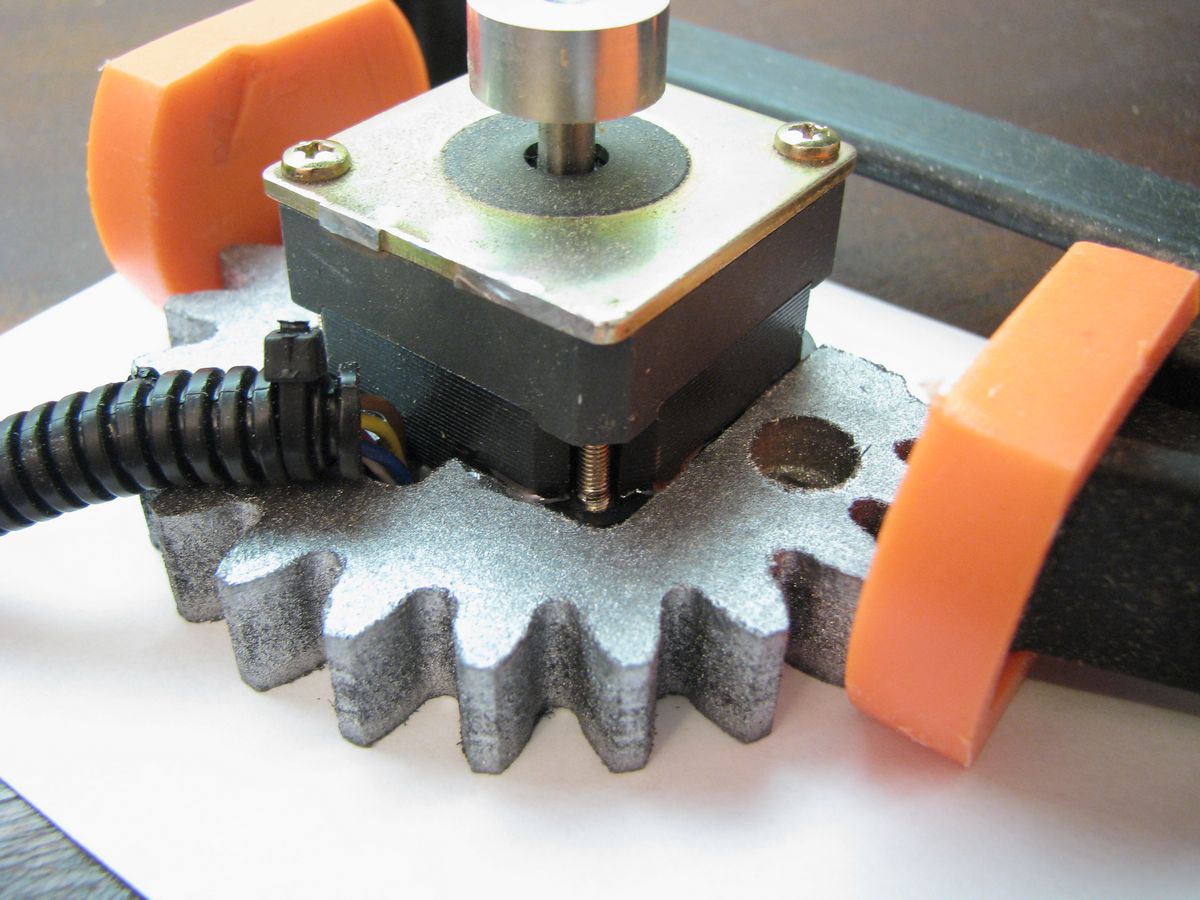
The motor is a unipolar stepper motor that has been harvested from an old 5 1/4 inch floppy drive. This is the motor that used to move the read write heads back and forth, to get one of this size and power you’ll need to find a nice old one. There are many sizes and styles of steppers so it may take a bit of digging to find a usable one. Modern floppy drives don’t have steppers with this level of torque.
This motor moves 1.8 degrees per pulse which means that with 200 pulses it will make one full rotation. Since it’s a unipolar motor it is simple for the PIC to drive it with only 4 transistors. You will also need to be aware of motors with different number of pulses per rotation however 200 is the most common.
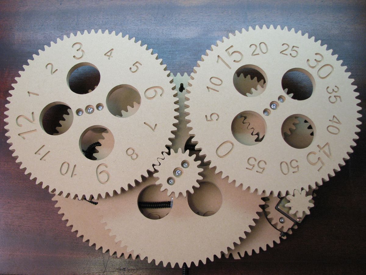
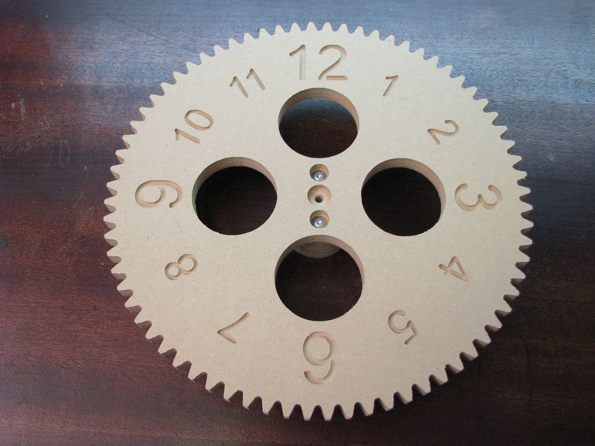
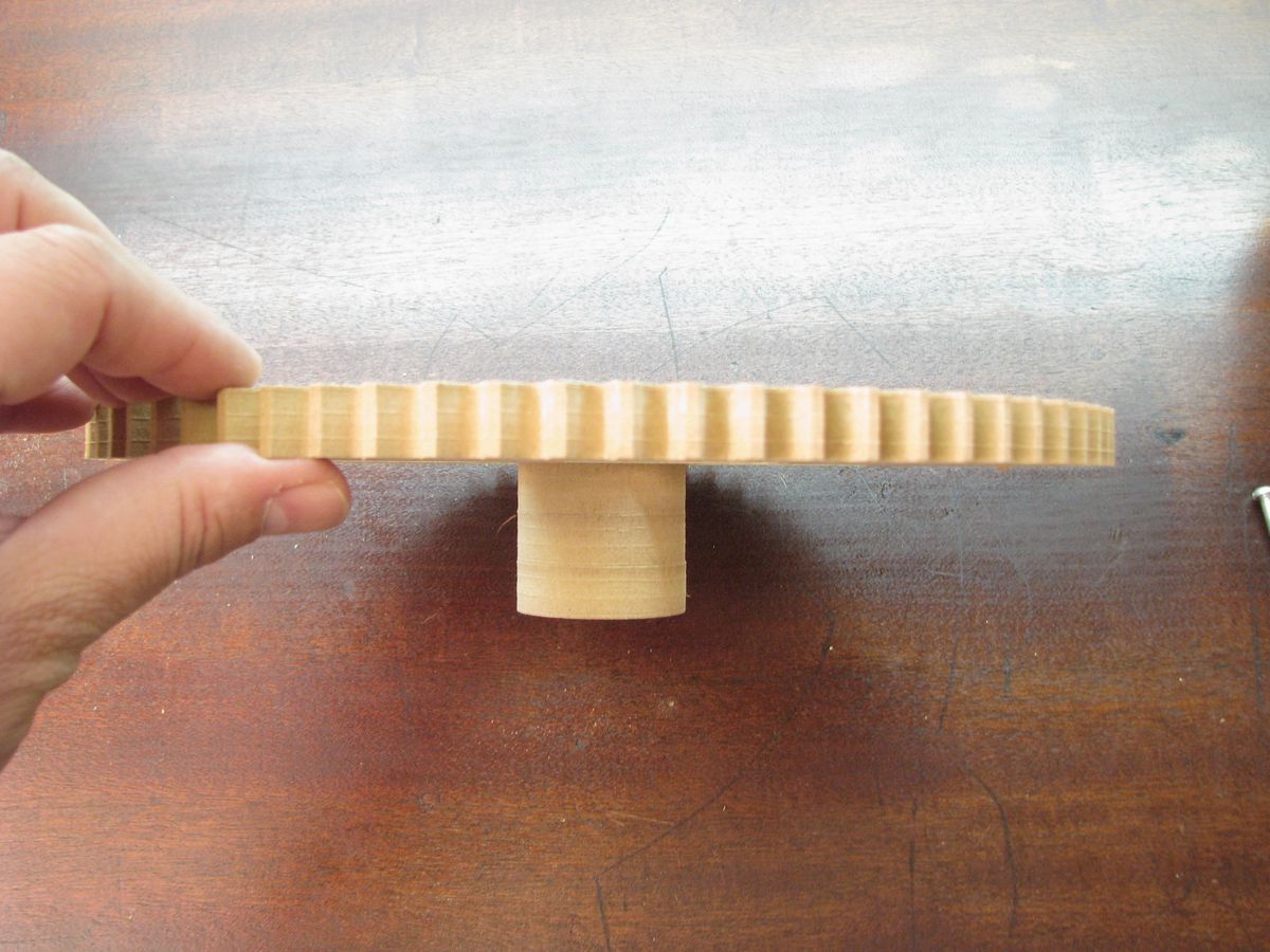
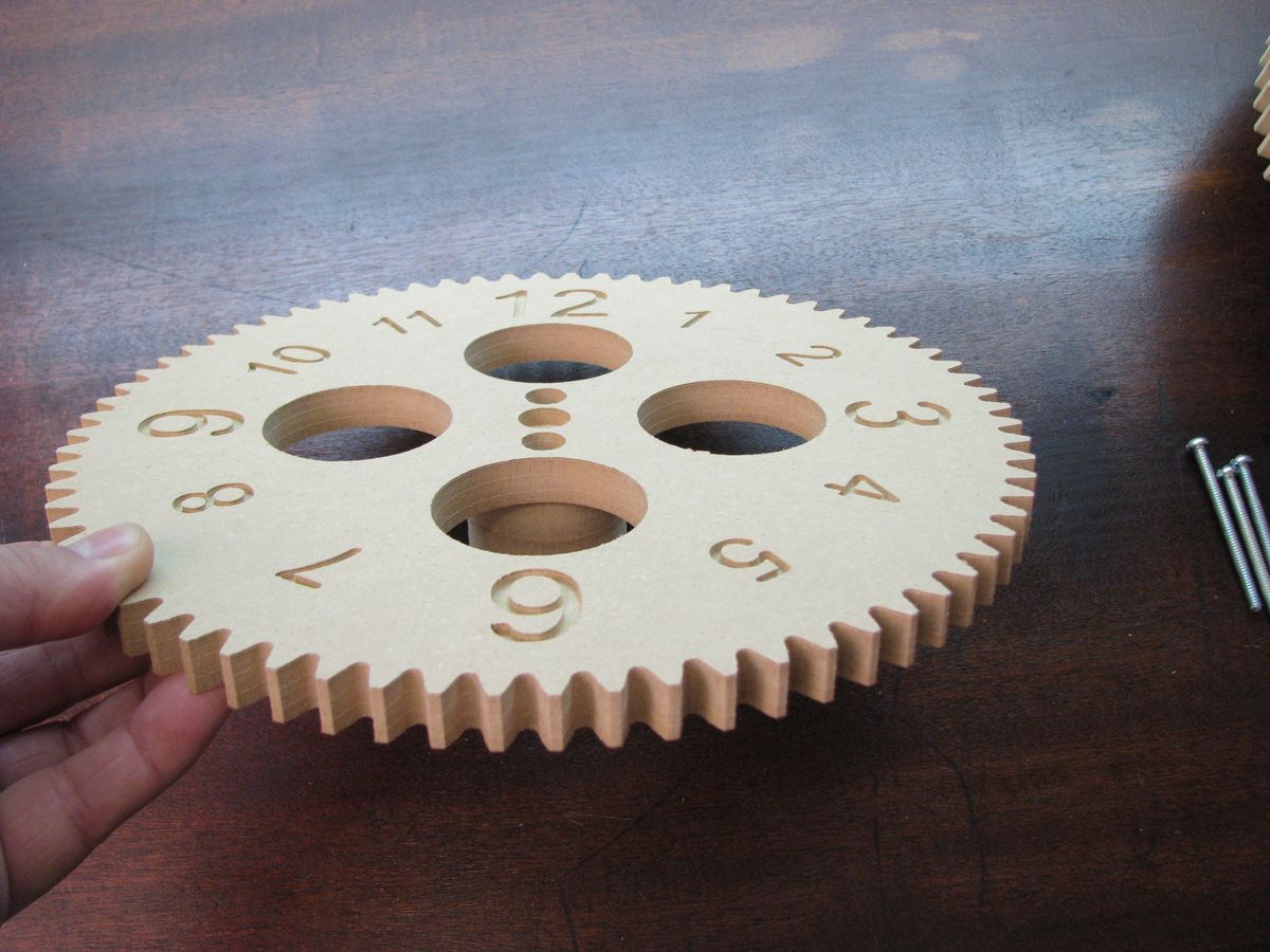
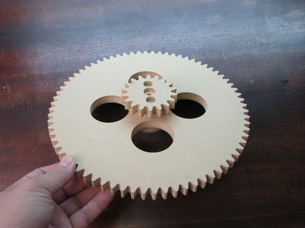
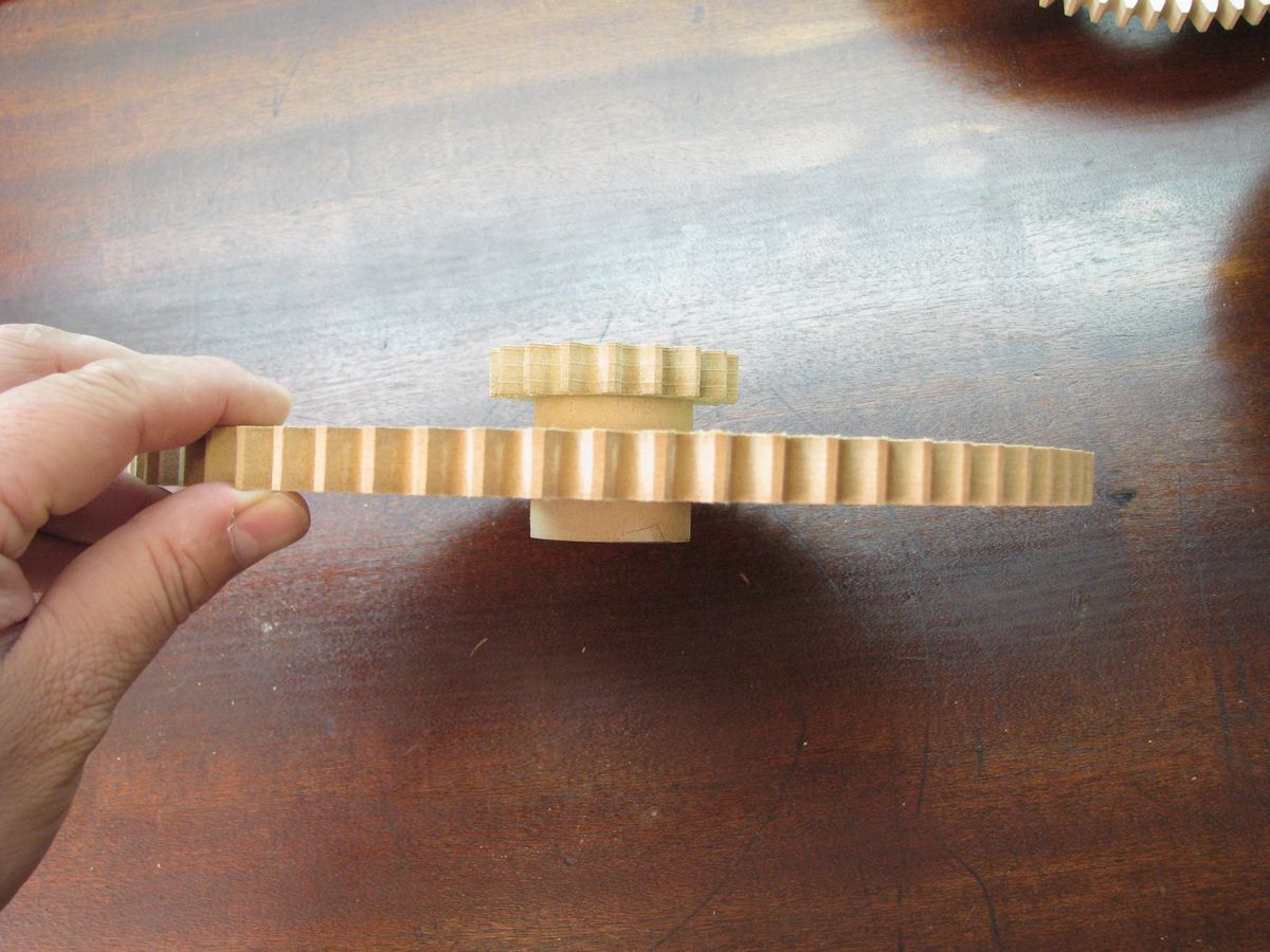
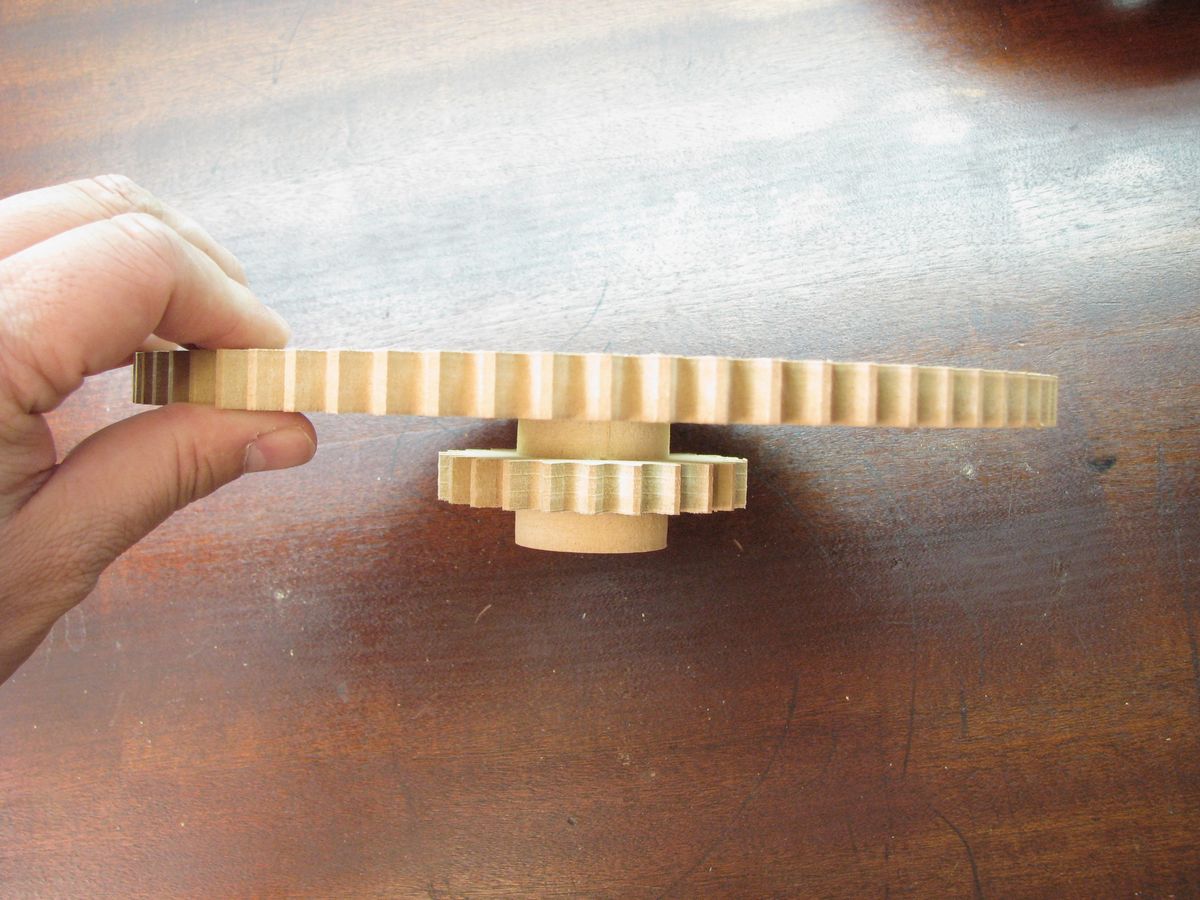
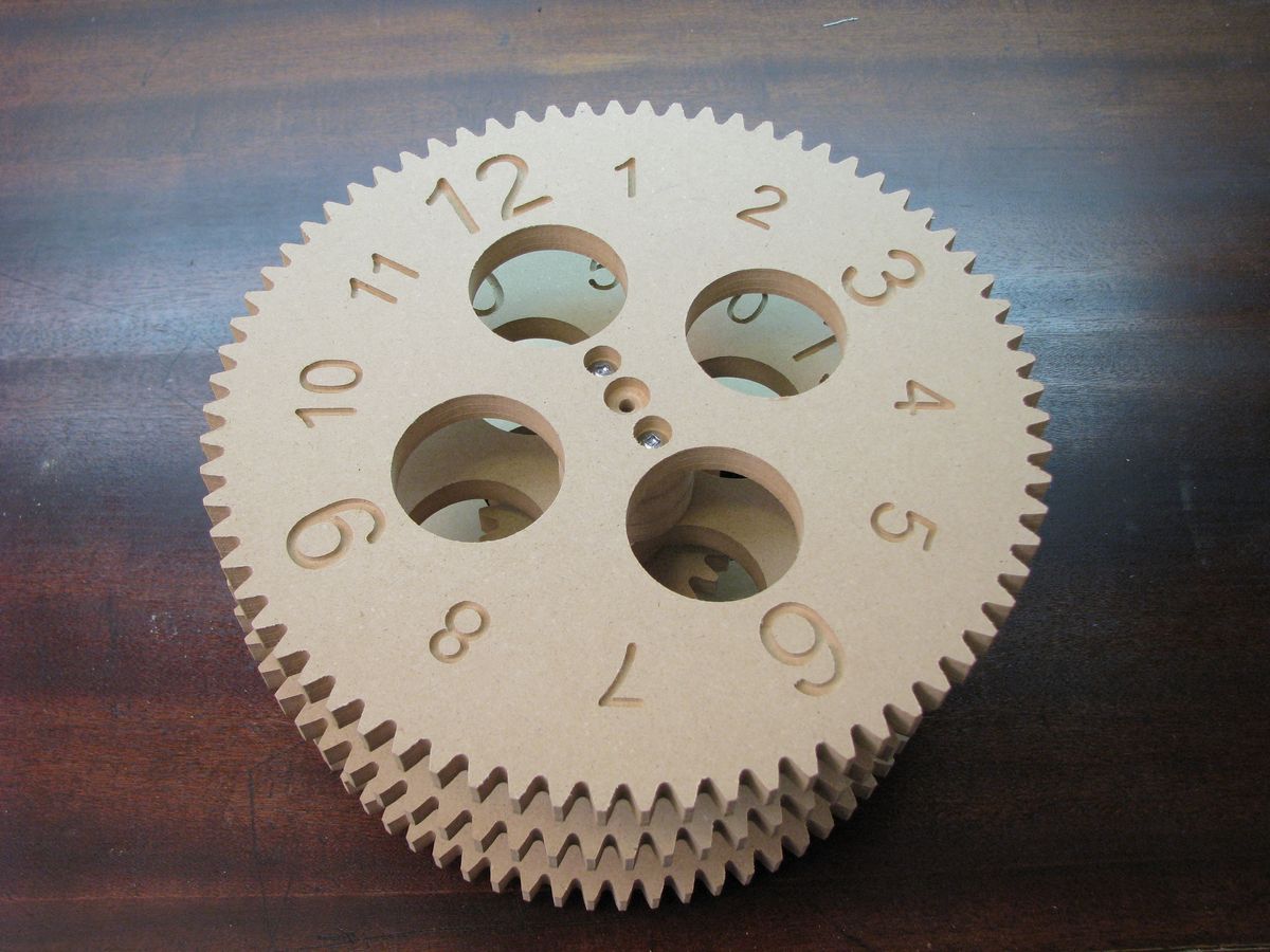
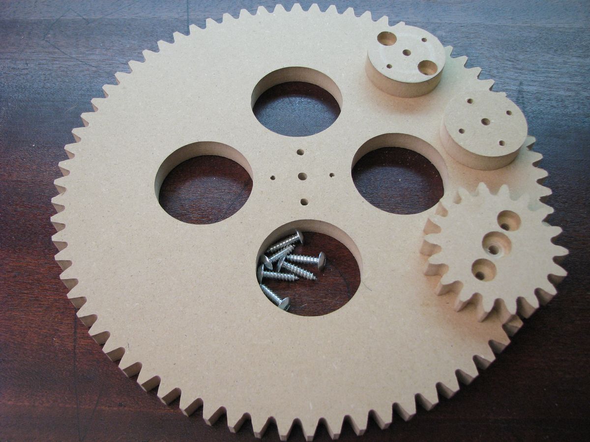
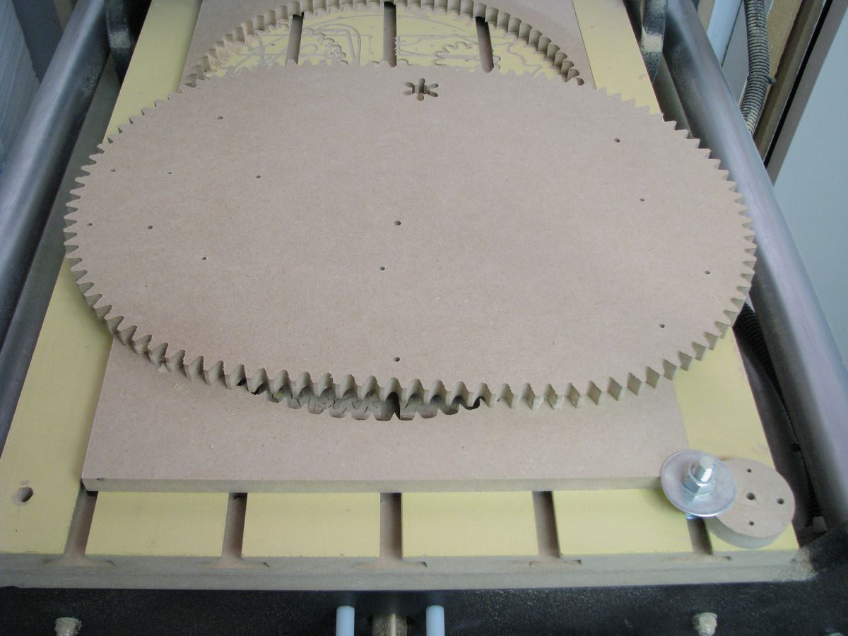
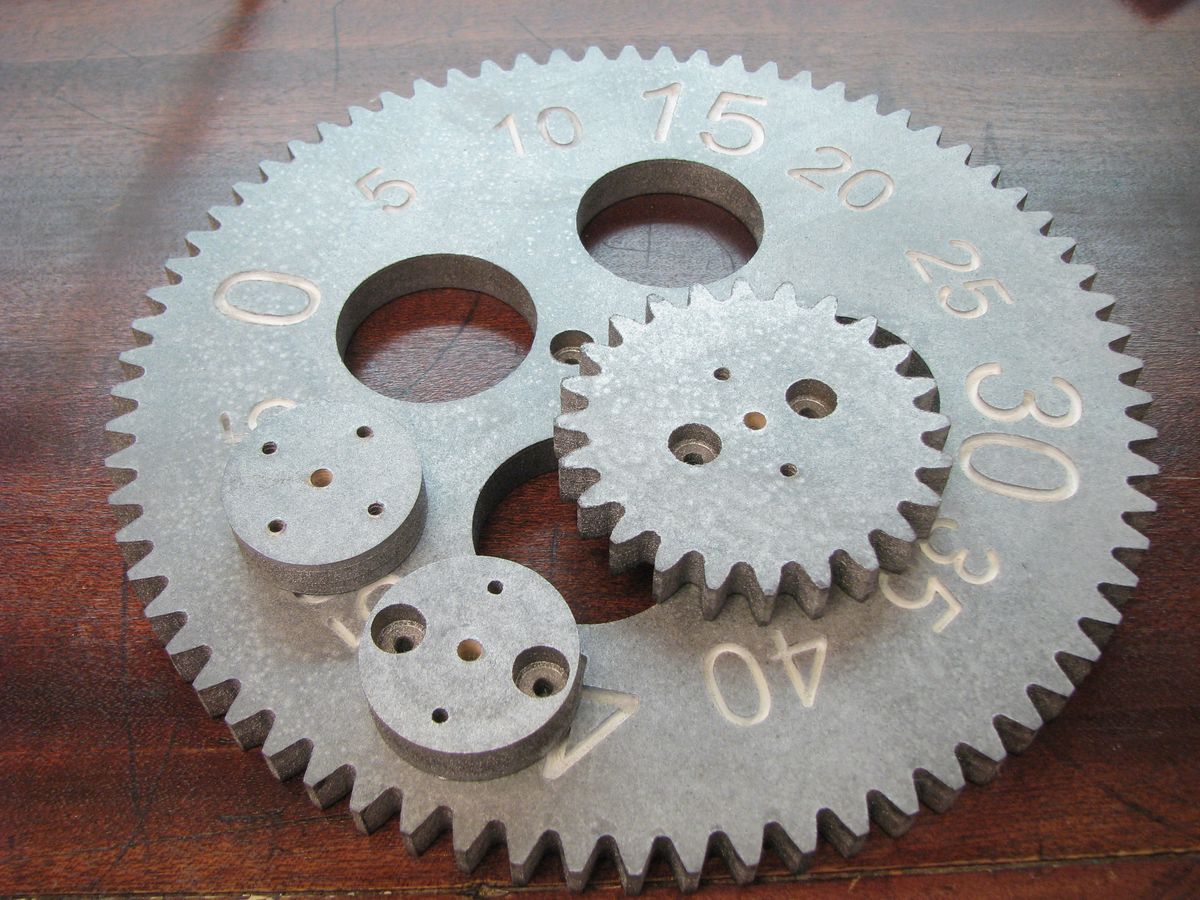
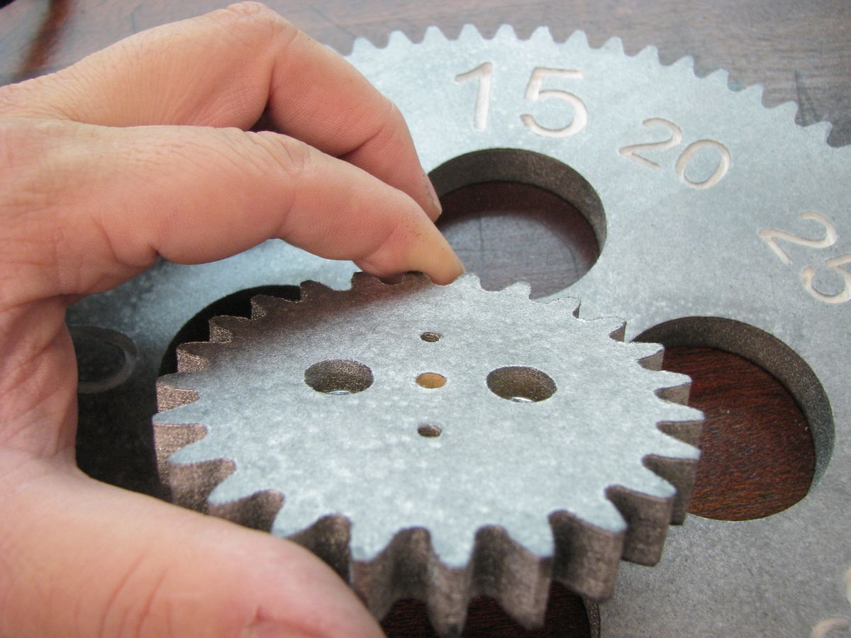
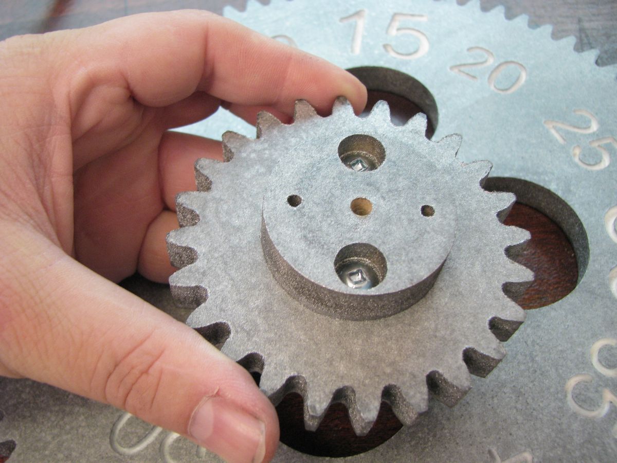
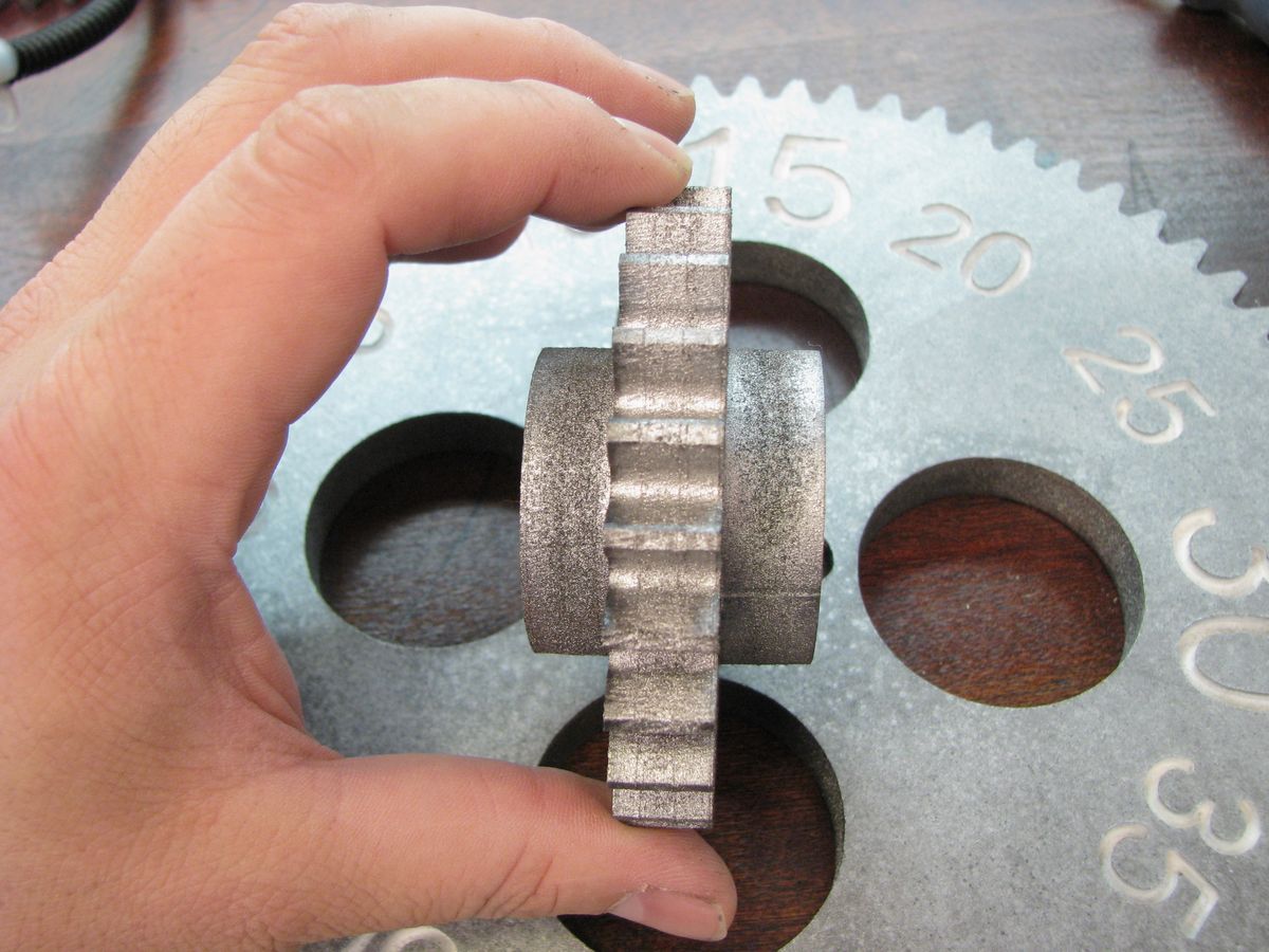
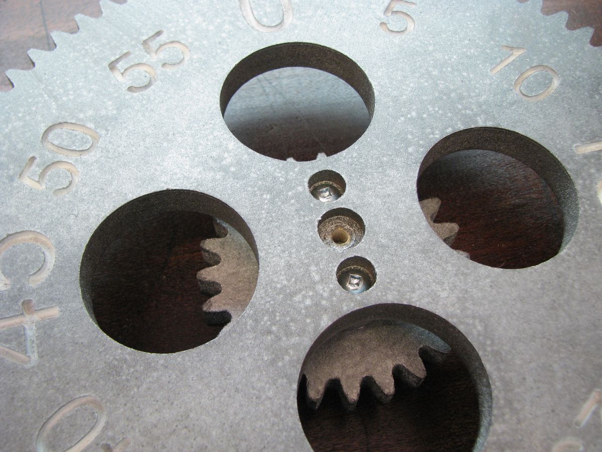
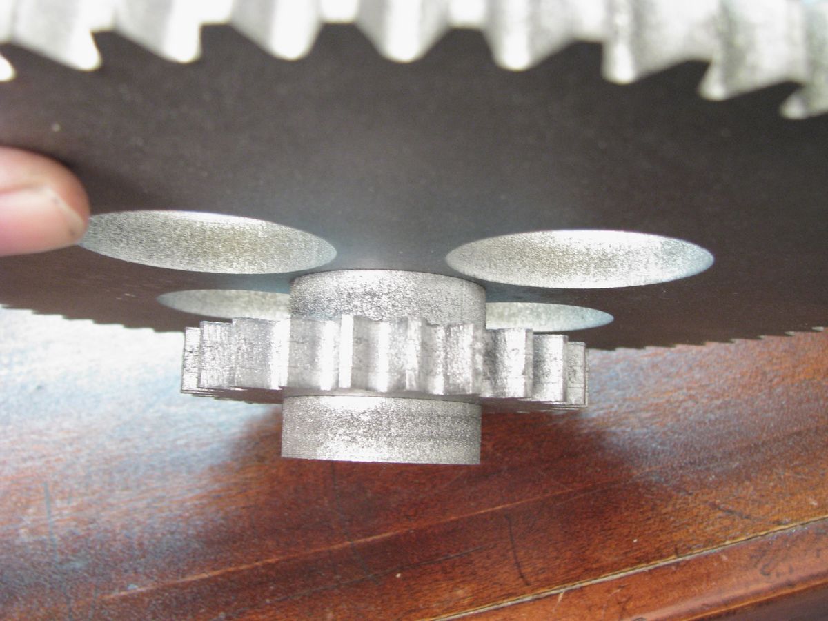
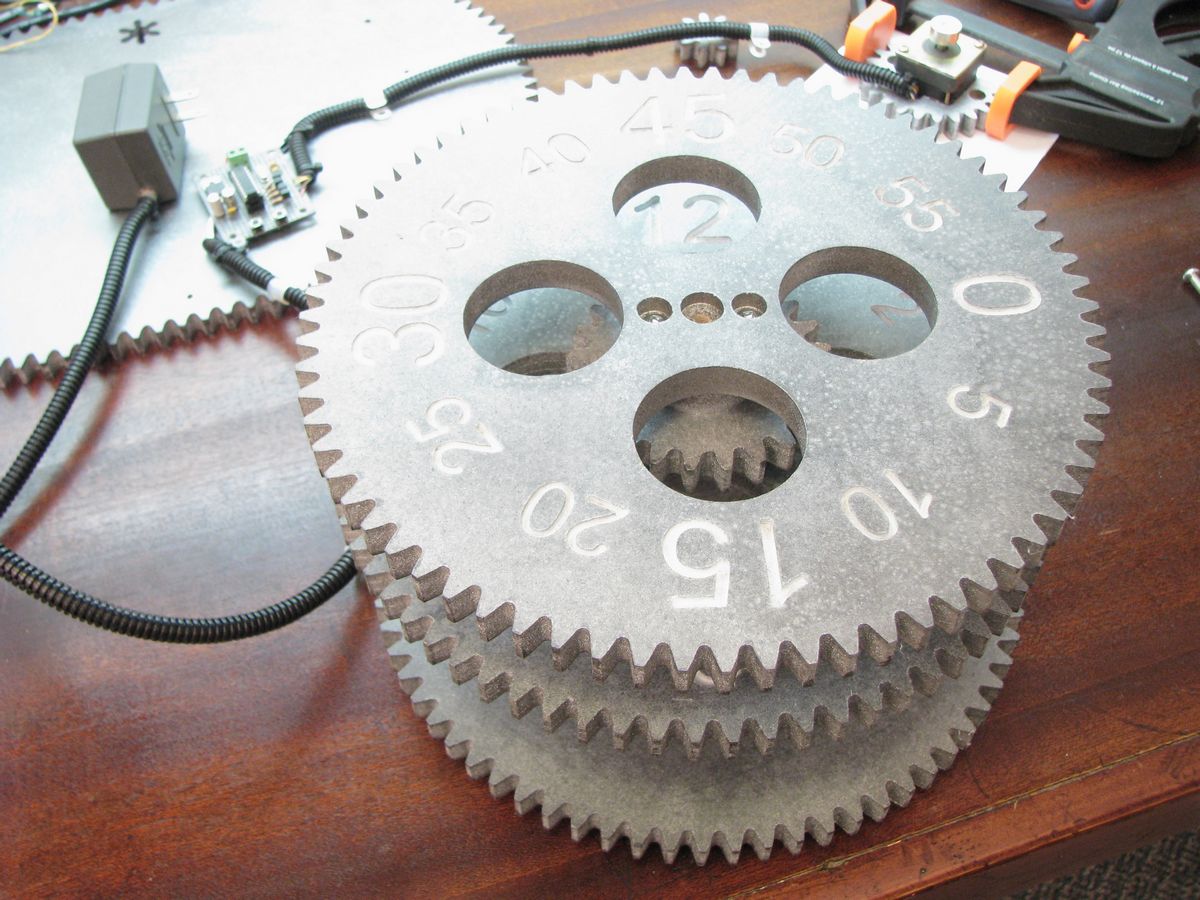
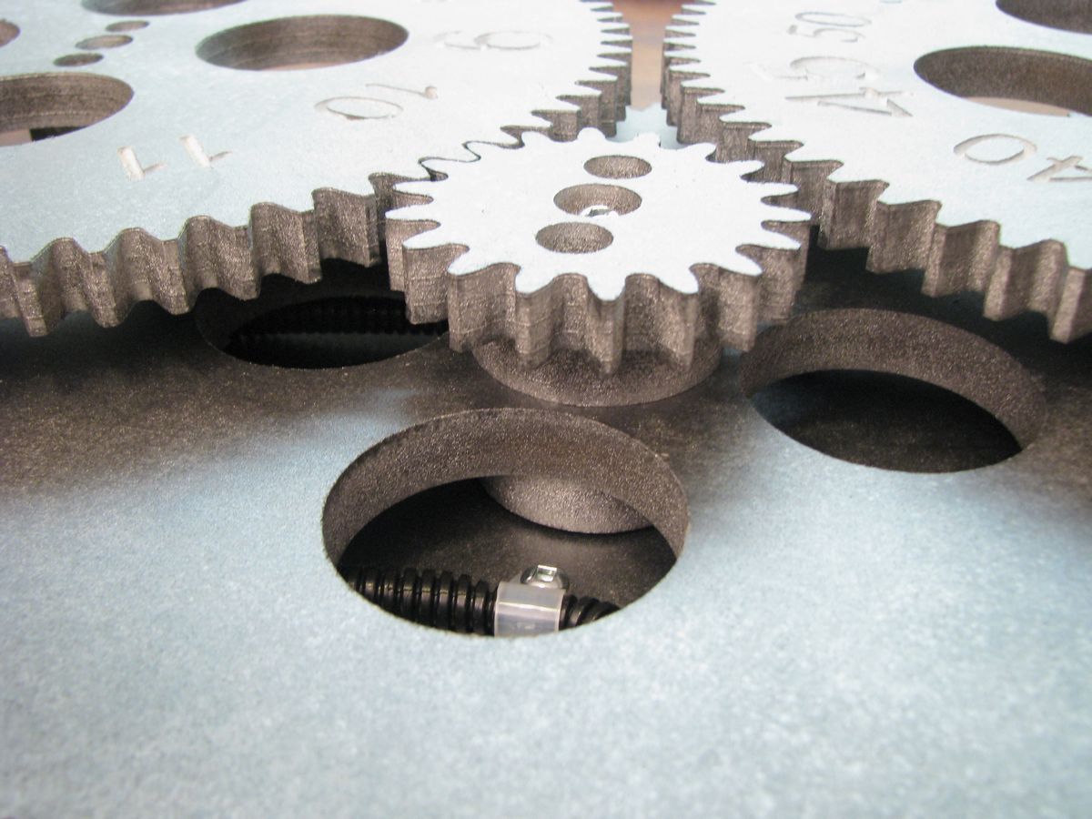
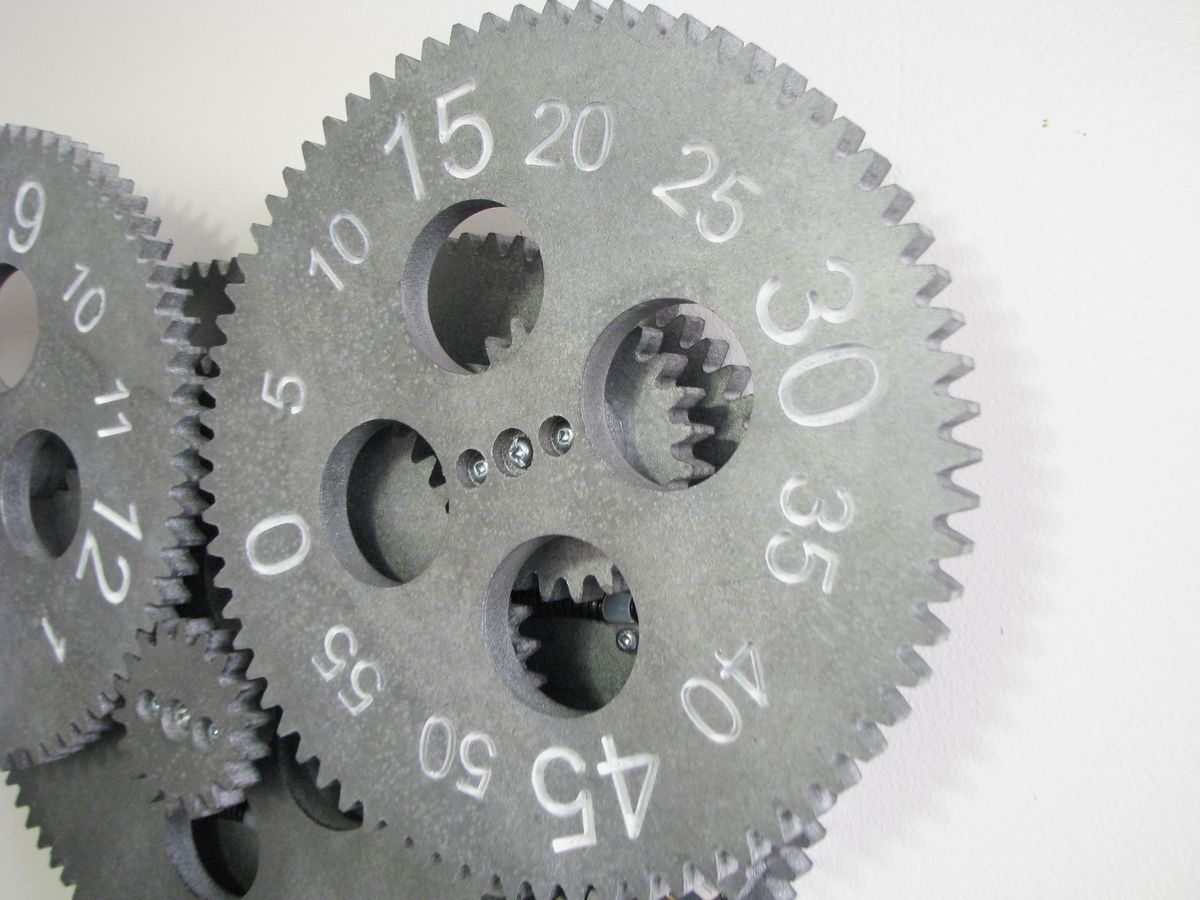
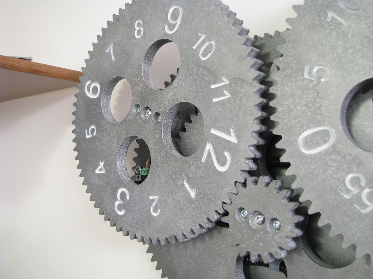
Gears
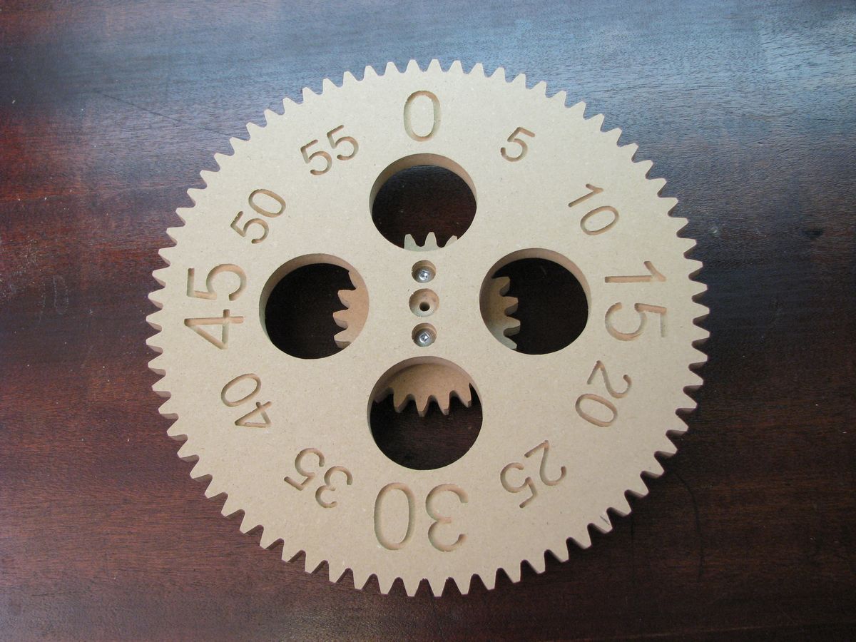
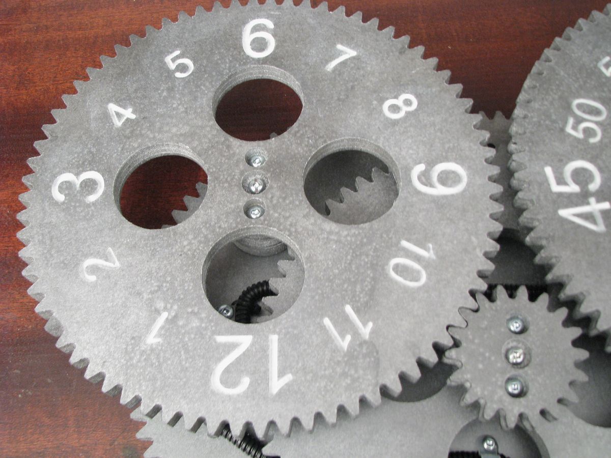
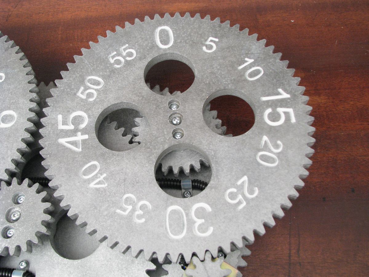
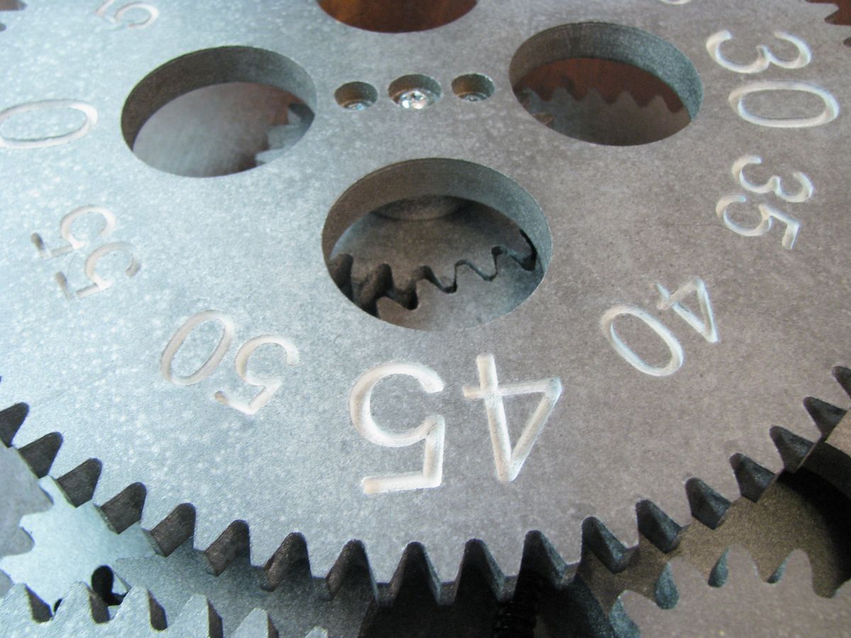
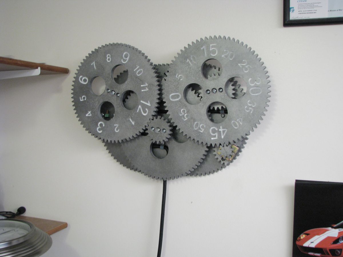
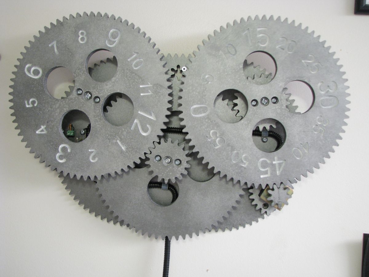
The gears are made out of MDF. They were painted to have a metallic look however the look I was going for was not achieved. Initially I was thinking of making the gears look like they were made of metal and left to rust for a few dozen years. I found some cool products that would give me that rusted effect but they were a bit too expensive. I settled for a can of Krylon Black Metallic Hammered Finish paint. The sample on the lid is a very nice black with subtle bit of gray. I think this might be from a bad batch since the final look is not as black as it should be. It also made taking pictures of the final clock a bit tough since even with modest lighting the glare was horrible.
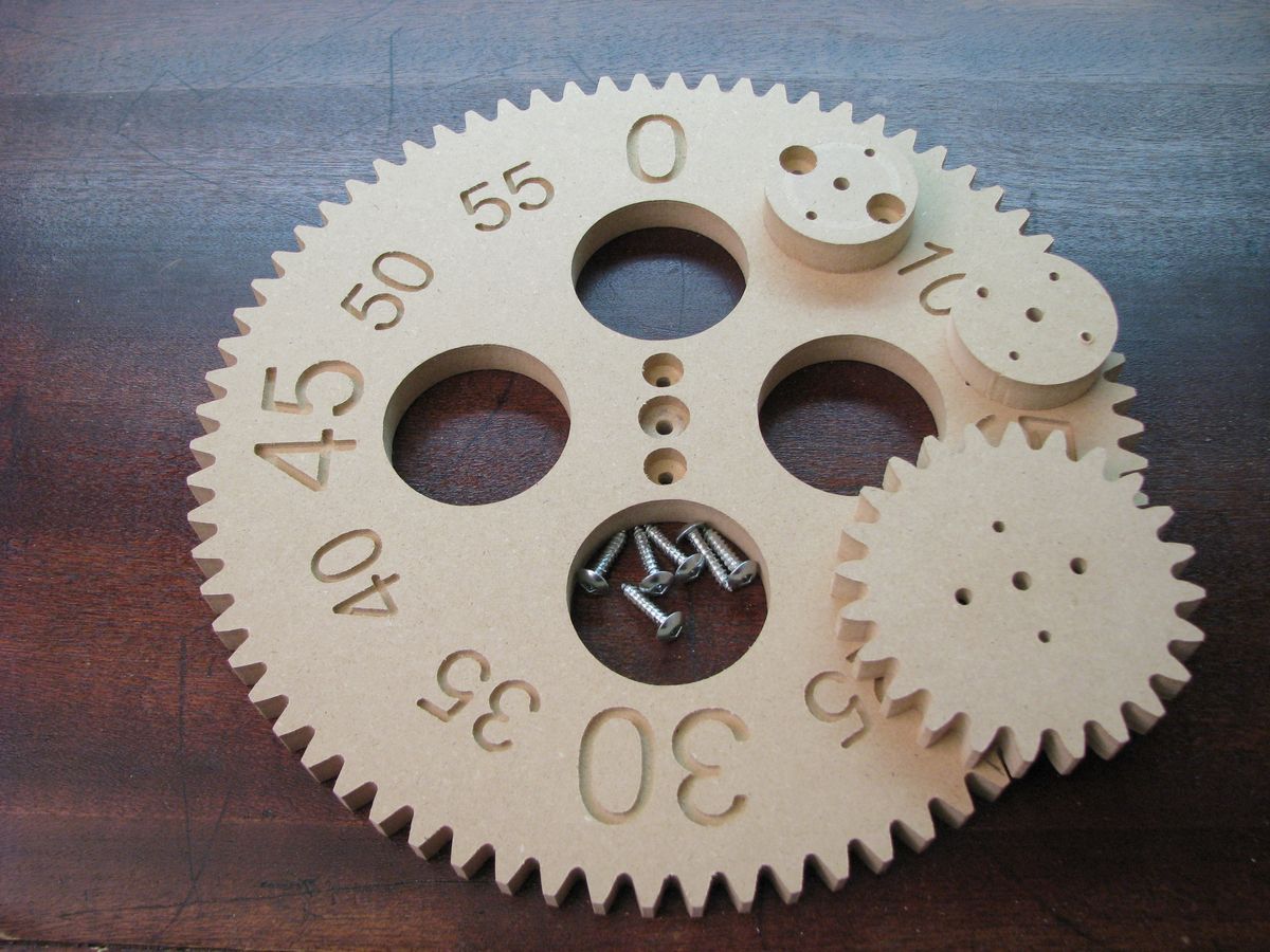
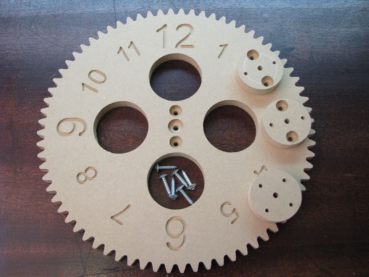
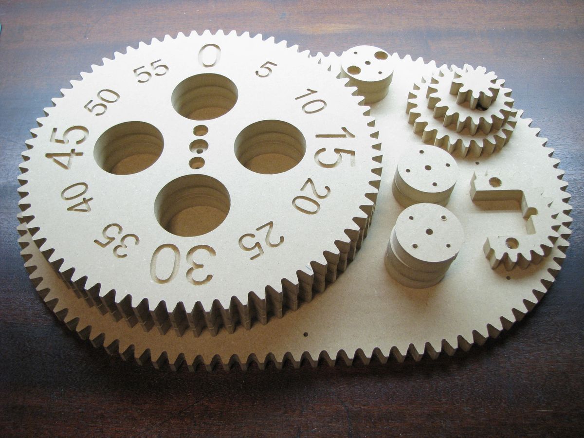
The gear arrangement is as follows:
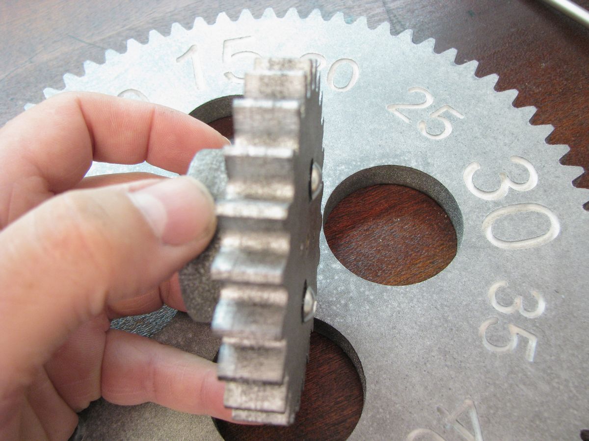
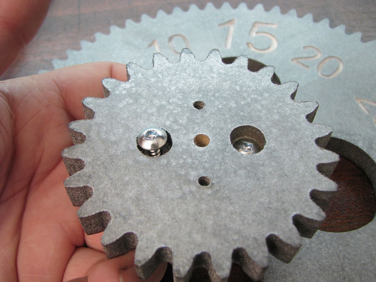
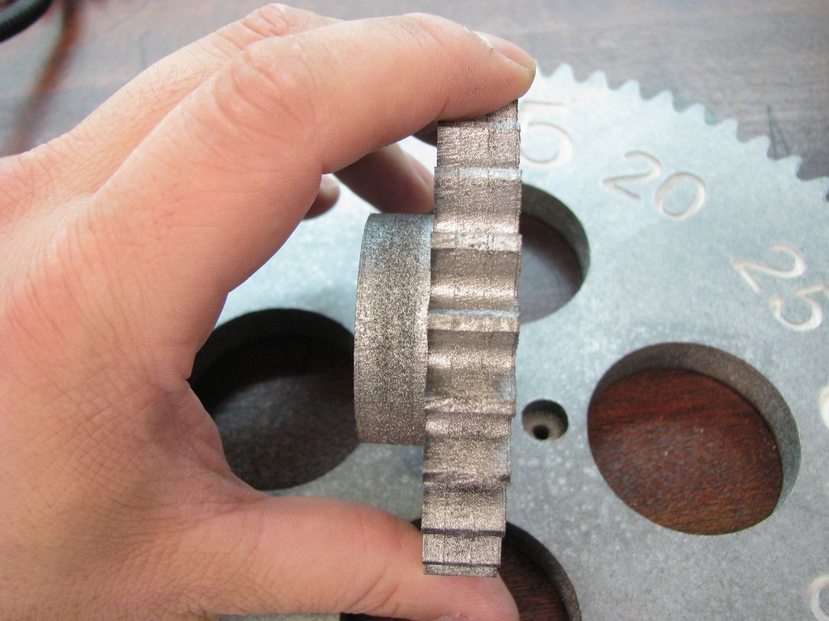
- 9 tooth motor gear
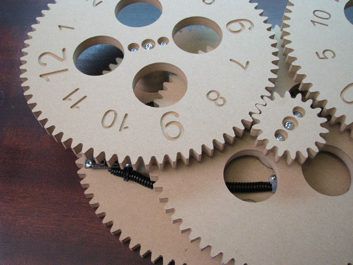
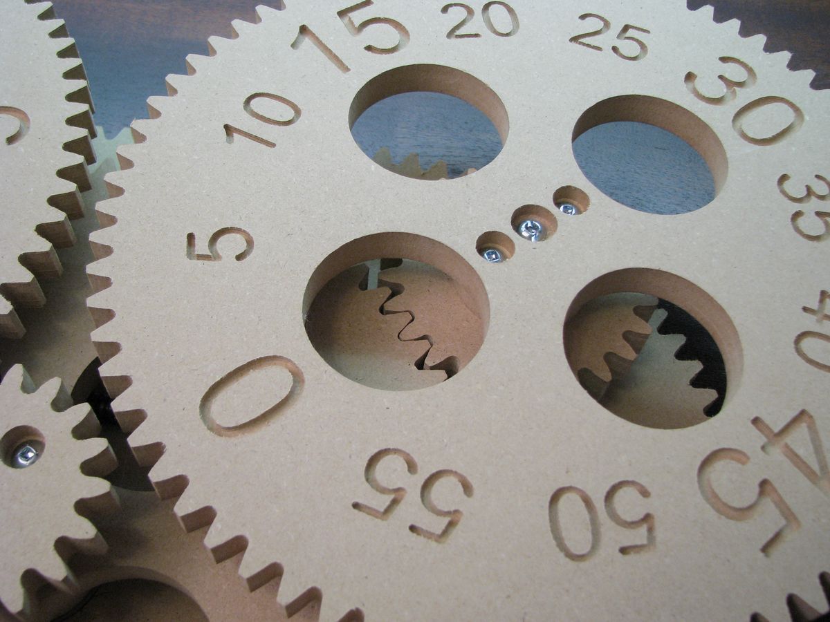
- 72 tooth minute gear with a 24 tooth secondary
- 72 tooth intermediate gear with a 18 tooth secondary
- 72 tooth hour gear
To achieve the correct timing the 9 tooth motor gear is advanced 4 steps every 9 seconds. By moving 4 steps at a time the motor routines can be simple since the motor is always at rest with the same coil energized.
Code
The code is basically split into two sections, there is an iterative loop that monitors the buttons for a change in state and checks if the internal clock has crossed the 9 second mark. If one of those conditions has occurred the stepper motor is driven appropriately.
The other section of code is interrupt driven and it keeps track of time. An interrupt is triggered every 0.1 seconds and adjusts an internal clock as needed. There is a true running clock inside, if you connect the clock PIC pin 6 to a computer serial port operating at 9600 bps you will see the internal clock values update once per second. The clock value in this case is arbitrary since it is never shown and will not be the same as what the gears are displaying but this same code will be used in future projects which will use this code display time.
Schematic

The schematic is just a quick back of the napkin design. I may cad up a proper design in the future. In the mean time if you have any questions about this one please ask.
Click on the image for a large version.
Download Code
If you are interested in burning your own chip you can get the HEX file here. If you would like to have a look at the source code that is available as a free item in the online store.
Download CAD Files

If you have access to a CNC machine you could cut your own clock parts. This zip archive has all of the DXF files for all of the clock parts. The g-code TAP files are also included if you prefer to use them. Please note that these files are only to be used to personal use.

on October 20th, 2009 at 11:52 pm
Nice clock design. I like the fact that you should be able to see it from across the room.
on October 21st, 2009 at 6:46 am
[…] is my latest creation, it’s a Gear Clock. It consists of a bunch of wooden gears, a PIC microcontroller and a stepper motor. The heart of […]
on October 21st, 2009 at 9:02 am
Hi,
Very nice project! Thank you for the explanation. I just have a question : Are the gears lazer cut? Did you do it at home?
Thanks
on October 21st, 2009 at 9:27 am
Nice idea. Very cool project to do and hung in our room walls.
on October 21st, 2009 at 9:39 am
[…] is my latest creation, it’s a Gear Clock. It consists of a bunch of wooden gears, a PIC microcontroller and a stepper motor. The heart of […]
on October 21st, 2009 at 10:03 am
[…] is my latest creation, it’s a Gear Clock. It consists of a bunch of wooden gears, a PIC microcontroller and a stepper motor. The heart of […]
on October 21st, 2009 at 10:22 am
Hi Bouba,
It was cut on a CNC machine.
Have a look at this project if you would like to see the machine in action.
http://hackedgadgets.com/2009/10/06/halloween-hanging-mobile-project/
on October 21st, 2009 at 11:48 am
[…] is my latest creation, it’s a Gear Clock. It consists of a bunch of wooden gears, a PIC microcontroller and a stepper motor. The heart of […]
on October 21st, 2009 at 12:31 pm
[…] is my latest creation, it’s a Gear Clock. It consists of a bunch of wooden gears, a PIC microcontroller and a stepper motor. The heart of […]
on October 21st, 2009 at 5:01 pm
[…] Parekh of Hacked Gadgets made this really nice looking gear clock using a PIC microcontroller, a scavenged stepper motor, and a bunch of wooden gears that he cut out […]
on October 21st, 2009 at 6:48 pm
[…] Parekh of Hacked Gadgets made this really nice looking gear clock using a PIC microcontroller, a scavenged stepper motor, and a bunch of wooden gears that he cut out […]
on October 21st, 2009 at 8:11 pm
[…] is my latest creation, it’s a Gear Clock. It consists of a bunch of wooden gears, a PIC microcontroller and a stepper motor. The heart of […]
on October 21st, 2009 at 8:16 pm
[…] Parekh of Hacked Gadgets made this really nice looking gear clock using a PIC microcontroller, a scavenged stepper motor, and a […]
on October 21st, 2009 at 9:02 pm
[…] Parekh of Hacked Gadgets made this really nice looking gear clock using a PIC microcontroller, a scavenged stepper motor, and a bunch of wooden gears that he cut out […]
on October 21st, 2009 at 10:01 pm
[…] and created a pretty cool wall clock. He explains how he did it fairly well in the video, but his site has even more detailed […]
on October 21st, 2009 at 10:21 pm
[…] and created a pretty cool wall clock. He explains how he did it fairly well in the video, but his site has even more detailed […]
on October 22nd, 2009 at 12:04 am
[…] and created a pretty cool wall clock. He explains how he did it fairly well in the video, but his site has even more detailed […]
on October 22nd, 2009 at 12:27 am
[…] and created a pretty cool wall clock. He explains how he did it fairly well in the video, but his site has even more detailed […]
on October 22nd, 2009 at 2:21 am
[…] If you fancy making one of these this weekend check out the full instructions here […]
on October 22nd, 2009 at 2:26 am
might be a nice idea to put a noticeable peg in the center of the minute and hour gears to orient the clock with so that someone wouldn’t have to guess where exactly the minute gear is.
on October 22nd, 2009 at 3:12 am
Hi Jeremy,
That is a great idea. One early idea I had was to drill 60 small holes around the perimeter of the clock and have an LED mounted under the wheel at the top center position. That way the actual time would be indicated by a glowing dot. I opted not to go that route since I thought the constant glow of the clock may drive me mad. 🙂
on October 22nd, 2009 at 5:54 am
Thanks!
on October 22nd, 2009 at 8:19 am
[…] Si vous voulez plus d’infos encore, genre pour faire la votre ça se passe par là . […]
on October 22nd, 2009 at 10:01 am
[…] feelings aside, [Alan] from Hacked Gadgets introduced us to his Gear Clock. While it’s not a new idea, and in fact we have a few around the office, his concept really […]
on October 22nd, 2009 at 11:23 am
I love the clock. I actually liked the unpainted look. I would absolutely love to have one of these. Perhaps you should make and sell these. I love the idea of home CNC’ed gears that make cool looking clocks.
If you make another version, I think it would like nice if it was unpainted. Also, I think it would look better if the back panel wasn’t a “fake gear” with the teeth on it. Last, I wonder if there is a way to make the current time more obvious. I thought about this for a little while and didn’t think of an obvious suggestion for you. The closest think I could think of is to rotate the numbers so that the current time is show at the point where the two gears are the closest. Maybe a different way to solve that would be to do a version that moved more traditional clock hands. If the gears were still home CNC’ed, It would still be just as cool IMHO.
Thanks so much for sharing!
on October 22nd, 2009 at 11:34 am
Very nice clock. Love the idea.
Any chance you publish the CNC (G-code) for making these?
on October 22nd, 2009 at 12:30 pm
[…] feelings aside, [Alan] from Hacked Gadgets introduced us to his Gear Clock. While it’s not a new idea, and in fact we have a few around the office, his concept really […]
on October 22nd, 2009 at 12:46 pm
[…] Plus d’infos sur le site du créateur […]
on October 22nd, 2009 at 1:30 pm
[…] is my latest creation, it’s a Gear Clock. It consists of a bunch of wooden gears, a PIC microcontroller […]
on October 22nd, 2009 at 1:39 pm
[…] out this awesome cool Gear Clock my friend Alan from HackedGadgets made! The Gear Clock features CNC, laser-cut gears coupled with […]
on October 22nd, 2009 at 4:50 pm
pcb, gear templates, gcode anything more?
on October 22nd, 2009 at 5:05 pm
Hi werejag and Crewdog,
I have had quite a few requests so I will be adding the gcode soon (hopefully within a week).
on October 22nd, 2009 at 5:09 pm
Hi Michael,
Thanks for the compliments. If there is a bit of interest I would be open to making these available in kit form.
on October 22nd, 2009 at 9:32 pm
Great clock! Have you thought about turning the numbers so that it’s easier to read? The time would read from the center of the clock. I did a quick mockup photo:
http://scenic-shop.com/files/pics/clock.jpg
on October 22nd, 2009 at 10:07 pm
Hi Matt,
That looks real cool. It reads very nicely. The only concern I would have is that 11:50 might look more like 12:50
on October 23rd, 2009 at 6:03 am
This is very cool looking and simple clock. I must build it myself.
on October 23rd, 2009 at 12:50 pm
Hi,
I would also be very interested in the CNC (g-code) for the creation of the gears. It would be much appreciated.
Thank you!
on October 23rd, 2009 at 1:03 pm
[…] Ever since I setup the CNC machine and built the controller housing I have been playing around with various ideas. Wooden gear projects have been around for a long time, and lots of people have made conventional gear clocks. I wanted to do something a bit different. This project combines some electronics and lots of wood. If you fancy making one of these this weekend check out the full instructions here […]
on October 25th, 2009 at 12:03 pm
[…] If you fancy making one of these this weekend check out the full instructions here […]
on October 26th, 2009 at 6:57 pm
This clock is absolutely awesome.
If you do get enough interest and you decide to offer kits, please let me know. I will certainly purchase a kit from you. This project is one for the books! I’d love to have one of these on my wall. You sir, are amazing!
TJ
on October 26th, 2009 at 8:06 pm
Hi TJ,
Thanks! The interest is growing so chances for a kit are looking good.
If you sign up to the news letter you would get an email if a kit is made available.
http://alan-parekh.com/mailing-list/
on October 27th, 2009 at 5:03 am
[…] is being used since it will have to accurately keep track of time for weeks and months. [via Alan-Parekh] Posted in General | Leave a […]
on October 27th, 2009 at 6:21 am
[…] [via Alan-Parekh] […]
on October 27th, 2009 at 7:25 am
[…] [via Alan-Parekh] […]
on October 27th, 2009 at 12:55 pm
[…] [via Alan-Parekh] […]
on October 27th, 2009 at 1:37 pm
[…] [via Alan-Parekh] […]
on October 28th, 2009 at 4:01 am
[…] Read | Permalink | Email this | Comments […]
on October 28th, 2009 at 4:02 am
[…] Read | Permalink | Email this | Comments read full article from Engadget « Litl Easel ‘web computer’ is cute as a baby-blue button […]
on October 28th, 2009 at 4:03 am
[…] Read | Permalink | Email this | Comments Go to Source […]
on October 28th, 2009 at 4:07 am
[…] Read | Permalink | Email this | Comments […]
on October 28th, 2009 at 4:08 am
[…] Read | Permalink | Email this | Comments October 28th, 2009 | Tags: Actual Time, Break, Clock, Clocks, Engadget, Fashion, Gadgets, Gears, Gizmo, Household, Lead, Mishmash, Mute Button, Nbsp, Parekh, True Joy, Watching The Time | Category: Uncategorized […]
on October 28th, 2009 at 4:12 am
[…] Read | Permalink | Email this | Comments […]
on October 28th, 2009 at 4:16 am
[…] Read AKPC_IDS += “521,”;Popularity: unranked [?]SHARETHIS.addEntry({ title: “Machined Gear Clock makes watching the time pass a true joy (video)”, url: “http://geoflip.com/?p=521” }); Technology […]
on October 28th, 2009 at 4:23 am
[…] Read | Permalink | Email this | Comments none Leave a comment […]
on October 28th, 2009 at 4:27 am
[…] Read More Tags: cnc, diy, gear, gear clock, GearClock, gears, hack, mod, time, timepiece, video No Comments Technology […]
on October 28th, 2009 at 4:27 am
[…] Read | Permalink | Email this | Comments Rate this topic: (No Ratings Yet) Popularity: 0 You can follow any responses to this entry through the RSS 2.0 feed. You can skip to the end and leave a response. Pinging is currently not allowed. […]
on October 28th, 2009 at 4:34 am
[…] Read | Permalink | Email this | Comments […]
on October 28th, 2009 at 4:35 am
[…] Read | Permalink | Email this | Comments Read the whole story on Engadget Share and Enjoy: […]
on October 28th, 2009 at 4:40 am
Nice clock, would look cool if it were make from real metal, also Im sure you thought of it so I ask, why did you not put a pointer at the top of the 2 main number dials so the numbers could be read with ease (Was it it a design choice?). When are you going into mass production 🙂
on October 28th, 2009 at 4:51 am
[…] Read | Permalink | Email this | Comments […]
on October 28th, 2009 at 4:58 am
[…] appeared on Engadget on Wed, 28 Oct 2009 03:58:00 EST. Please see our terms for use of feeds.Read | Permalink | Email […]
on October 28th, 2009 at 4:59 am
[…] Read | Permalink | Email this | Comments […]
on October 28th, 2009 at 4:59 am
[…] appeared on Engadget on Wed, 28 Oct 2009 03:58:00 EST. Please see our terms for use of feeds.Read | Permalink | Email […]
on October 28th, 2009 at 4:59 am
[…] Read | Permalink | Email this | Comments […]
on October 28th, 2009 at 5:00 am
Hi Chris,
I was originally going to have a pointer, then the thought was to have many tiny holes drilled around the outside edge of the gear and have a small LED located in the top center position so that there would be a tiny dot of light that indicated the actual time. I didn’t end up doing that however since it is actually quite easy to read the time without it and I thought that the constant on light might be a bit much.
on October 28th, 2009 at 5:00 am
[…] appeared on Engadget on Wed, 28 Oct 2009 03:58:00 EST. Please see our terms for use of feeds.Read | Permalink | Email […]
on October 28th, 2009 at 5:00 am
[…] Read | Permalink | Email this | Comments Of Wolf and Tap Tap Revenge: Metallica on iPhone Pandora Opens Its Box A Bit More With Twitter, Facebook, And Gifting Integration […]
on October 28th, 2009 at 5:01 am
[…] appeared on Engadget on Wed, 28 Oct 2009 03:58:00 EST. Please see our terms for use of feeds.Read | Permalink | Email […]
on October 28th, 2009 at 5:01 am
[…] appeared on Engadget on Wed, 28 Oct 2009 03:58:00 EST. Please see our terms for use of feeds.Read | Permalink | Email […]
on October 28th, 2009 at 5:01 am
[…] appeared on Engadget on Wed, 28 Oct 2009 03:58:00 EST. Please see our terms for use of feeds.Read | Permalink | Email this | Comments Related ArticlesBookmarksTags […]
on October 28th, 2009 at 5:02 am
[…] appeared on Engadget on Wed, 28 Oct 2009 03:58:00 EST. Please see our terms for use of feeds.Read | Permalink | Email this | Comments Author: Darren Murph […]
on October 28th, 2009 at 5:02 am
[…] appeared on Engadget on Wed, 28 Oct 2009 03:58:00 EST. Please see our terms for use of feeds.Read | Permalink | Email […]
on October 28th, 2009 at 9:30 am
i would happily pay at least £100 for it u should sell it
on October 28th, 2009 at 3:04 pm
[…] (Quelle: Alan Parekh) […]
on October 29th, 2009 at 2:02 am
[…] żaden model sklepowy i najprawdopodobniej nie wejdzie do produkcji seryjnej, jednak Alan na swojej stronie internetowej udostÄ™pniÅ‚ wszystkie informacje potrzebne do budowy takiego zegara. SkÅ‚ada siÄ™ on z 6 kół […]
on October 29th, 2009 at 11:44 am
[…] Ayrıntılı bilgi ve video burada. […]
on October 29th, 2009 at 3:50 pm
[…] Read | Permalink | Email this | Comments […]
on October 29th, 2009 at 10:02 pm
[…] Ayrıntılı bilgi ve video burada. […]
on October 29th, 2009 at 10:30 pm
[…] reading 動画:手作りメタルギア・クãƒãƒƒã‚¯Read | Permalink | Email […]
on October 30th, 2009 at 1:45 am
[…] This post was mentioned on Twitter by PZ*, James Lewis and Zoltan Szentesi, crowz. crowz said: http://bit.ly/2f0WAb 機械時計フェãƒã¨ã—ã¦ã¯ã„ã„ã‹ã‚‚。ã§ã‚‚æ¯è»Šã®èª¿é”ã«ãŠé‡‘ãŒã‹ã‹ã‚Šãã†ã€‚ […]
on October 30th, 2009 at 3:40 am
Hi lalm20,
I sent you an email.
on October 30th, 2009 at 3:40 am
FYI. The response has been great! We will be making this project into a kit.
on November 3rd, 2009 at 5:24 am
[…] Alan Parekh’s Electronic Projects] Share this on FacebookTweet This!Share this on del.icio.usStumble upon something good? Share it on […]
on November 12th, 2009 at 1:28 pm
WE NEED TO BUY A GEAR CLOCK.
HOW IN POSSIBLE.
WE HAVE OFFICE IN MIAMI.
WAIT YOUR NEWS.
on November 12th, 2009 at 2:58 pm
Hi Jorge,
Please sign up to the mailing list, when clock kits are available you would then be notified.
http://alan-parekh.com/mailing-list/
on November 21st, 2009 at 11:12 pm
[…] and created a pretty cool wall clock. He explains how he did it fairly well in the video, but his site has even more detailed […]
on November 27th, 2009 at 12:09 pm
Hey,
I’m having trouble as to where to add a pointer on the gears… My one is almost finished, will try to add some pics later, amazing one though, so i would like your guid as to where a pointer may be attached to view proper timing, i was planning on adding an led as you suggested but that would be irritating to the eye… a mock up of an image would be much appreciated if you could
again many thanks i love your project
on November 27th, 2009 at 3:12 pm
Hi Nas,
I haven’t thought it through completely so I can’t help with a mock up but I wonder if some type of wire that is bent around from the back would be the best? Something that is coat hanger thickness might be thick enough to indicate the current time number.
on November 28th, 2009 at 9:23 am
Thank YOU
on November 29th, 2009 at 2:43 am
Hey
Well i’ll try that out and a few other methods,
thanks again
on December 10th, 2009 at 10:05 am
Hey
Could you help me a bit with the components, can you write the list of components used?, I have seen the schematic and gotten an idea of whats being used but im having some trouble, please add the quantity needed too!
Is that an 18-Pin Retention Contact holding the PIC?
Thankyou
on December 10th, 2009 at 10:45 am
Hi David,
We are working on a kit, when the kit is complete there will be descriptions of everything used. But there is nothing exotic there. Some resistors, a voltage regulator, some caps, etc.
If you have a specific question I can help you out though. The thing that the chip is plugged into is called a socket. Since the chip pinout is called DIP, it is a DIP socket. If you Google “DIP Socket” you will find many examples.
on December 10th, 2009 at 12:26 pm
Thanks, i understood that part, another question is: the voltage regulator 7805 is pin 2 connected to GND and the rest of the components requring GND connection?, do i need to use another diod for the 5v or out put at pin 3 or 7805 does its job?
on December 14th, 2009 at 3:51 pm
I thought you would want to know that this site does not display right on my mobile (iphone).
on December 16th, 2009 at 3:44 am
Hi David,
On the regulator the left pin is the input, the center pin is the ground and the right pin is 5 volts out. Yes everything that is connected to ground is common to the center pin of the regulator.
There is no additional diode needed. The input diode is not a crucial part either, it is just there to protect from the circuit being hooked up backwards or to a AC adapter by accident.
on December 17th, 2009 at 5:34 am
Hey
thanks again, another question which type of unipolar stepper motor did you add?im asking voltage use wise as in 3v 5.1v, 24v( i knw its 1.8 degree sa you specified it)
on January 15th, 2010 at 11:25 am
Hi Dave,
Sorry about the delay in response. I somehow didn’t see this message until now. It was a 12 volt stepper motor that was taken out of an old floppy drive (5 1/4 inch one).
I just noticed that the hand drawn schematic doesn’t indicate where the common stepper wire is connected. Since it is a 12 volt motor the common wire of the stepper would be connected to pin 1 of the regulator (that is the 12 volt power before it is regulated).
on January 22nd, 2010 at 7:18 am
Hey
Hmm thnx, though i couldnt get a hold of a 12VDC stepper motor, i ripped one off a floppy drive which was unipolar 1.8degree,6v and had six wires.. should i connects both of the centre wire taps(both common wires) to the 1st terminal of the voltage regulator. or the 6v stepper motor wont work with this driver, thnx alot
on January 22nd, 2010 at 12:17 pm
Hi Dave,
Yes, both commons should be tied to pin 1. But since your stepper isn’t 12 volt you will also need to use a resistor in series to allow your stepper motor to operate within its specifications. I would meter the resistance of one of the stepper coils and use a resistor of similar value.
on January 23rd, 2010 at 5:05 am
Hey Alan,
I got the stepper to work… but the transistor connected to coil 1 overheats, so i removed the connection of coil 1 it started to work, though im not sure of its accuarcy(it does hit the 9 second mark), the diods soldered the correct way, the side without the ring is connected to +12v,so maybe either a faulty resistor or transistor.. any suggestions?
Thnx again
on January 23rd, 2010 at 2:57 pm
How much current is the stepper pulling? When the unit is not stepping (most of the time) it is being held in place by coil 1. In the kit version (which will be released soon) there is a PWM option which will hold the coil with less power.
on January 24th, 2010 at 7:48 am
Resistance of each coil is 0.7 ohms which i got from a reference data sheet(can’t find the data sheet of my stepper motor), I’ll get a multimeter and get the accurate readings…(stepper motor is a 6v)6v/0.7 Ohms = 8.5714…Amperes??maybe…what if i add around 10 ohm resistors, to the base of the transistors???or do you suggest getting a power transistor…??btw im using an AC/DC adapter for power supply and it is set to 12VDC
on January 28th, 2010 at 4:05 am
Is your 12 volt power supply adjustable? If it is set it for 7 volts. This should be high enough for the voltage regulator (for the chip) to function and will lower the draw from the stepper motor. Where did you see that spec? I don’t think that motor would be from your floppy drive because as you calculated it would be drawing tons of current that I am sure your plug in power supply can’t handle.
If it is truly a 0.7 ohm stepper then you will need to find a different one. The transistors are only rated for between 500 and 600mA tops so they would not handle that current.
Once you get a meter let me know what the actual measurement is.
on January 31st, 2010 at 10:26 am
Hey Alan quick question! will a 48 unipolar stepper motor do the job?
on January 31st, 2010 at 12:03 pm
Hi Dave,
It will when the kit comes out, the new kit controller will work with 48 or 200 step steppers.
on February 7th, 2010 at 1:17 pm
[…] have been putting the final touches on the Gear Clock kit which is made up of wooden gears. I have a new appreciation of the effort it takes to make […]
on February 22nd, 2010 at 10:10 am
Thanks for the great project. I cut the gears with your gcode and it worked real well. I was not able to locate a motor and was hoping that I might be able to purchase just the electronis and motor. If this is possible let us know. I know there are many cnc folks on various hobby sites that would be interested and it could be a major seller.
on February 22nd, 2010 at 11:06 am
Hi John,
We have had lots of inquiries about that, the motor, PCB and electronics will be available as a kit this week.
on May 7th, 2010 at 5:18 am
Hi
Just learning to program PIC’s using PIBbasic. I have been going through your code for the clock and although I understand it, there is one part I cannot get my head round.
‘set the timer to 3036 (OBDC Hex) to allow for the timer to count to 62500
TMR1L_Setpoint var byte bank0
TMR1H_Setpoint var byte bank0
TMR1L_Setpoint = $DC
TMR1H_Setpoint = $0B
Cannot understand how these HEX values in a 16 bit registry limits count to 62500. I can see where value of 62500 comes from but then I lose it. I presume it is something to do with the overflow. Checked data sheets but these don’t help. Would appreciate your explanation.
on May 7th, 2010 at 6:00 am
Hi
I’ve figured it out. So simple. You sometimes miss the obvious.
Overflow value 65535 – 3036 (0BDC) = 62499. I feel stupid at times. Still not sure about the 1 difference though.
Regards
Paul
on May 23rd, 2010 at 1:42 pm
What I dont understand is how youre not even more popular than you are now.  Youre just so intelligent.  You know so much about this subject, made me think about it from so many different angles.  Its like people arent interested unless it has something to do with Lady Gaga!  Your stuffs great.  Keep it up!
on September 11th, 2010 at 7:23 am
Hi:
I am close to releaseing a softwar epackage to support this kind of work.
You can find gears of all kinds at http://www.gearotic.com in the very near future.
Art
on September 11th, 2010 at 11:28 am
Hi Art,
That looks like it will be an interesting gear making package.
on November 3rd, 2010 at 3:28 am
This is an amazing piece of work. I’d like to do it myself but it looks hard to do if you don’t have the proper tools and equipment. Very nice!
on February 16th, 2011 at 6:43 pm
[…] cog from a mechanical clock designed by Alan Parekh before it had it’s final wipe […]
on February 21st, 2011 at 9:50 am
[…] When you are laser etching some stuff there isn’t much contrast in the end result. There are rub on products that you simply buff off the excess. Only issue is you have a short working time before it is on everywhere for good. I am all about using products that you already own and didn’t know it could be used in a new and creative way. That is exactly what James Williamson has done with the crayon. Who would be looking for a black crayon right after they had laser etched some plastic? Well after you see the results you might be that person. You simply rub the crayon onto the plastic piece letting it fill in all the grooves that are etched, wipe off the excess with some alcohol and heat to melt and level the remaining wax. If you the clock gear looks familiar you are right, James looks to be building one of my gear clocks! […]
on June 18th, 2011 at 5:11 pm
often thought about making acrylic see through clock with the hour and minute hands on two discs lit up from the base different colours and likewise the numerals on square face bottom lit with say gold circles on face to hide the rotating disks driven by stepper motor in base,a carriage type clock like this would look fatastic on the mantelpiece
vic
on November 30th, 2011 at 10:33 pm
I like so much your job, and i would like well if you want to, to have your relation for every gear, what are the size of every gear and how much gear did you use…
sorry for my english, im studying english..! and mechanics
Thanks in advance..
on January 26th, 2012 at 7:08 am
[…] electronics controller for this clock. Since this clock doesn’t operate in the same way the Gear Clock did some custom firmware was […]
on January 7th, 2013 at 5:42 am
Pls provide more specification for gear will ask my engineering students to do this project.
on January 8th, 2013 at 2:37 pm
Hi Dora,
You can find the information in the article above. Is there something specific that you are looking for?