
PWM Fan Controller

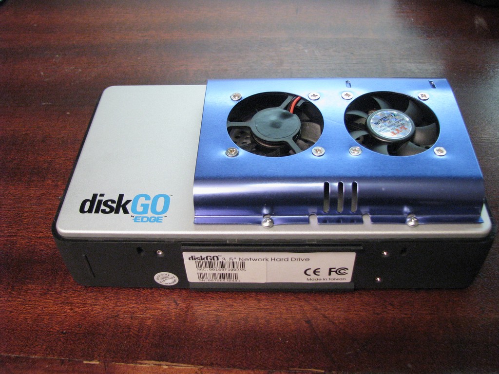
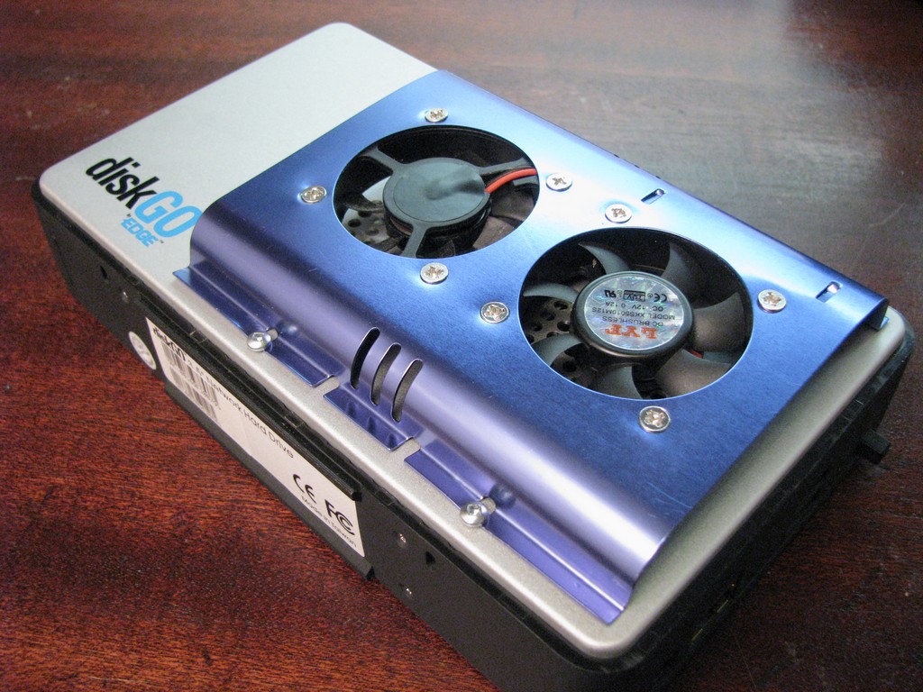
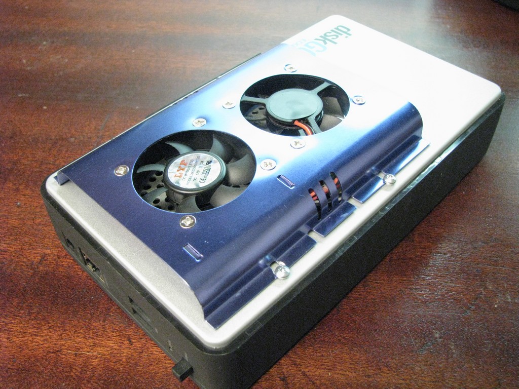
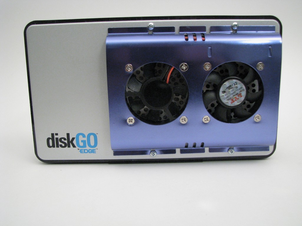
I have an external Ethernet enabled hard drive that is connected to my LAN and it gets lots of use. I have noticed that after a few hours of hard use the case is quite hot to the touch. I’m sure the design is fine and the heat that is generated is within the tolerance of the drive but I wanted to give it some ventilation and some forced air cooling. This project adds a cooling feature that only functions when it’s needed.
Overview
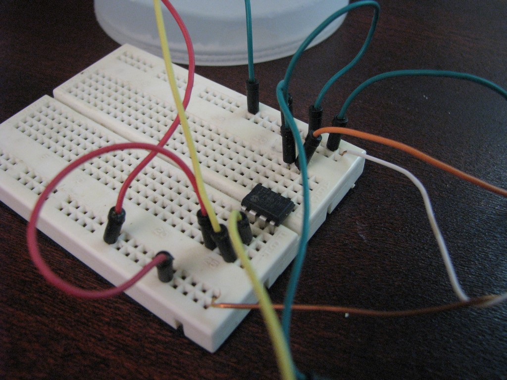
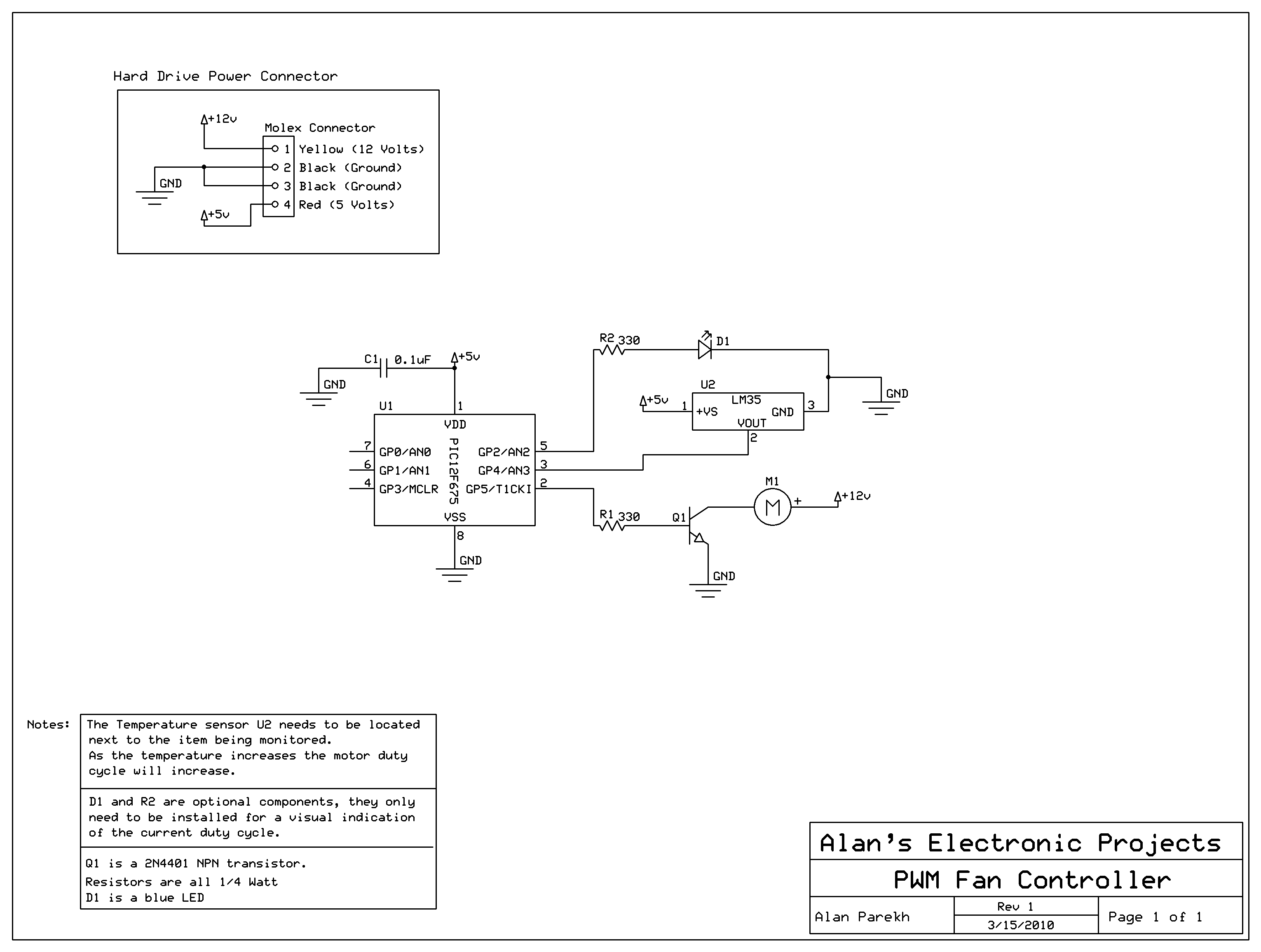
The heart of the PWM Fan Controller is a PIC 12F675 microcontroller. This microcontroller is reading the analog output of a LM35 temperature sensor using a ADC (analog to digital converter) . The resulting digital value is converted to a temperature and a fan is powered proportionally to how hot the sensor is. The sensor is mounted against the hard drive chassis so it is measuring the actual drive temperature and not just the air temperature inside the housing.
Video 1 of 4 – Intro and LM35 Sensor Overview
Block Operation
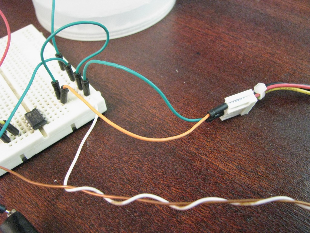
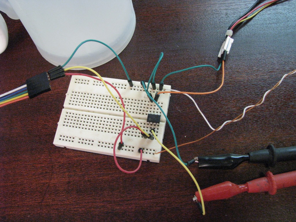
The system is quite simple, a temperature sensor will be connected to the input of a microcontroller. There will be two outputs, one for operating the fan and one for operating a status LED. During construction a serial output will also be used for debugging purposes.
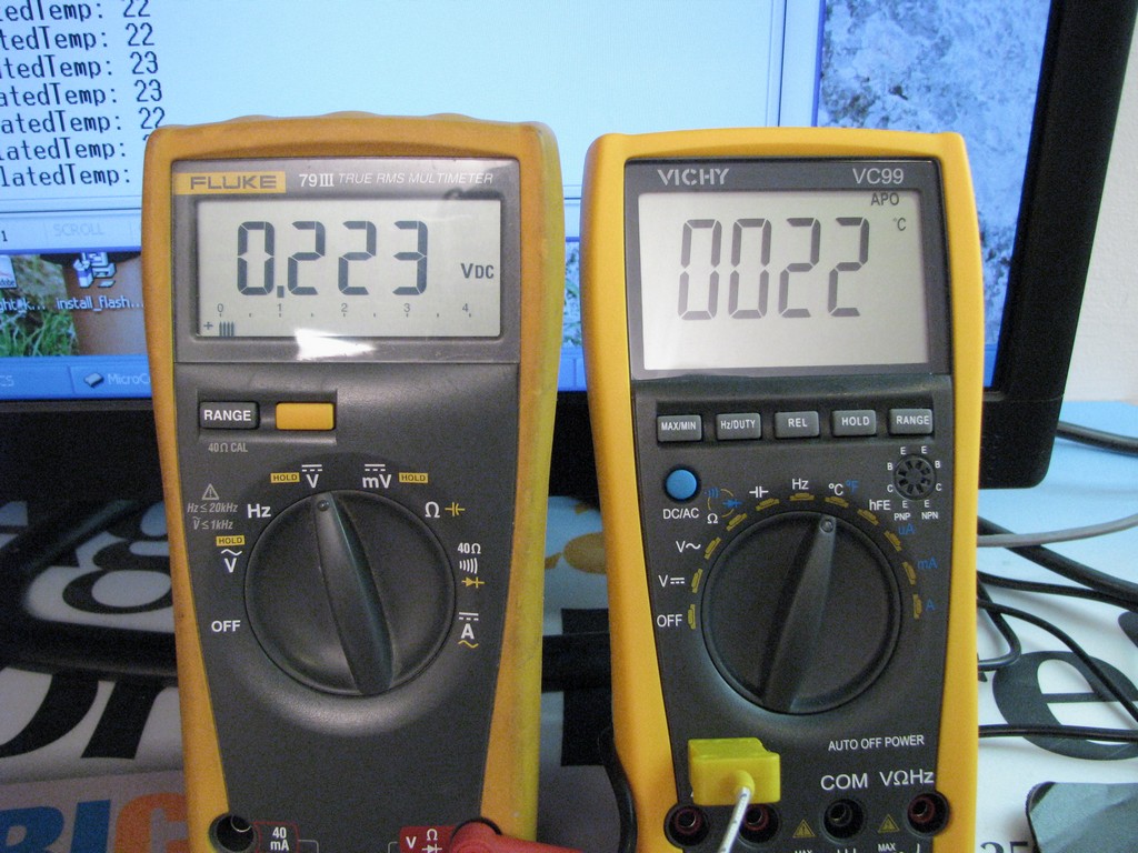
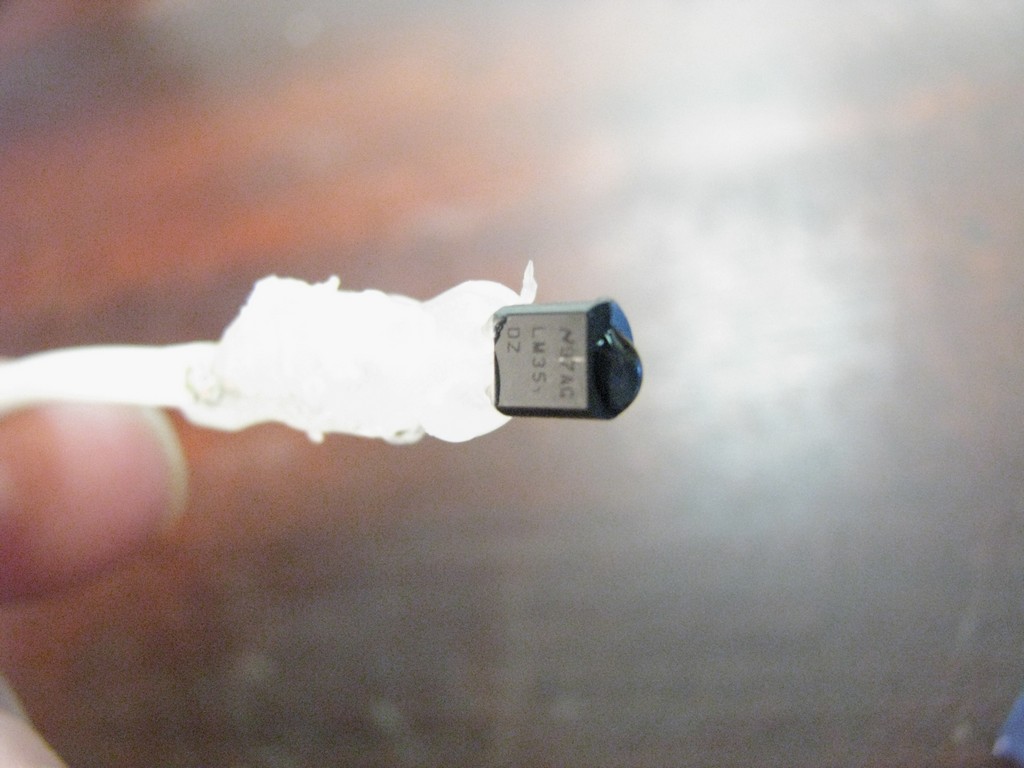
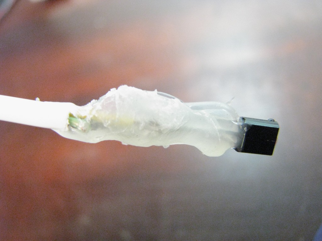
LM35 Temperature Sensor
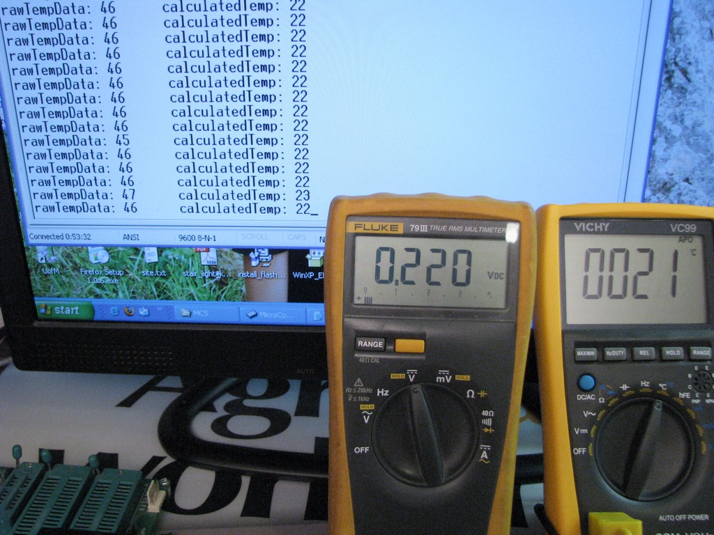
The LM35 temperature sensor package being used is the TO-92, it is small enough for this project and is leaded so that we can easily connect it to some wires. It is also nice since we can extend it by simply plugging it into a 0.1 inch female wire harness. This is a Celsius device and since the output is 10mV per degree it is very simple to calculate the temperature. It is even nice and simple to directly view the temperature on a multimeter as can be seen in the video.
Video 2 of 4 – Reading Data with the Microcontroller
Analog to Digital Temperature Conversion
The LM35 outputs 10mV per degree Celsius, this can be read very easily on the meter but unfortunately is isn’t quite that simple to read it within the microcontroller. The output of the LM35 is connected to an ADC (analog to digital converter) so that we can get a usable reading from it, but first we need to do a small calculation.
The analog input has a range of 0 to 5 volts and the digital resolution is 10 bits. This means that the 0 to 5 volt range will be represented by a number from 0 to 1023 in the microcontroller. If we divide 5 volts by 1024 we get the number of volts per digital increment. In this case it is 0.004883 volts per increment. So if the voltage was 1 volt on the microcontroller pin we would expect to have a reading of around 204 as the digital number (1/0.004883).
To convert the digital value to a degrees Celsius number we need to do a bit of math. If we take the digital result and multiply it by 49 then divide it by 100 we will get a result that is very close to the correct result. The calculation looks a bit weird since we are working with integer math. With integer math the information after the decimal is lost. For example 25/3 would be 8 (not 8.333).
Here is a full example. If we have a temperature of 15 degrees Celsius the voltage out of the LM35 would be around 10mV * 15 = 0.15V we know that each 0.004883 volts is one count for the digital side of the ADC therefore 0.15V / 0.004883 V = 30.73 this would provide a value of simple 30. Finally if we use the formula 30 * 49 / 100 = 14.7 but it would be stored as 14.
Video 3 of 4 – PWM Control Setup
Fan PWM Temperature Range
The intent of this project is to keep the fan off when the drive is cool and since the drive spins down after about 5 minutes of inactivity the drive is allowed to naturally cool down. Also when the temperature is moderate the fan speed should be slow which will be as quiet as it can be. To come up with the temperature range of just running slow to running at full fan speed I used the data from the Google hard drive failure report.
Here is the table of fan speeds based on temperature that was used.
| Temperature (deg C) |
Fan PWM Value |
| 35 | 0 |
| 36 | 30 |
| 37 | 30 |
| 38 | 30 |
| 39 | 40 |
| 40 | 50 |
| 41 | 60 |
| 42 | 70 |
| 43 | 80 |
| 44 | 90 |
| 45 | 100 |
There is no speed of 10% and 20% since many fans don’t like to be run with that little power. In this design 30% is the lowest amount of power used. When the fan initially gets powered up from an off state it gets about 1 second of full power to ensure it starts up properly.
Video 4 of 4 – Completion
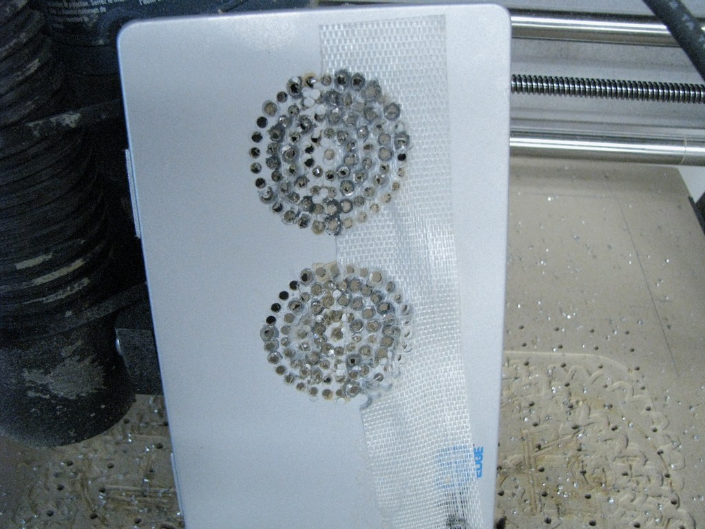
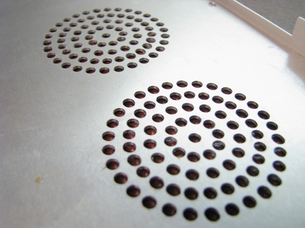
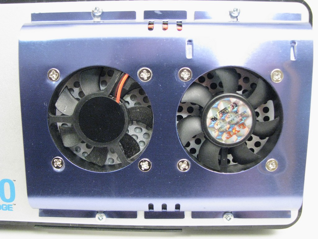
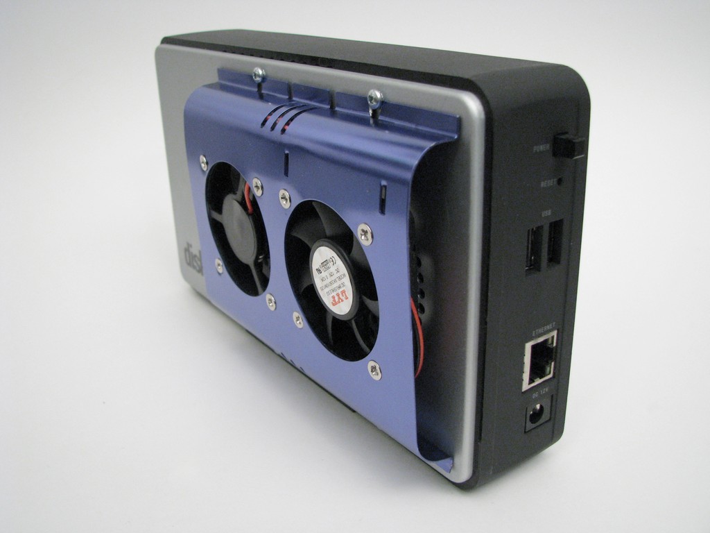
Ventilation Holes
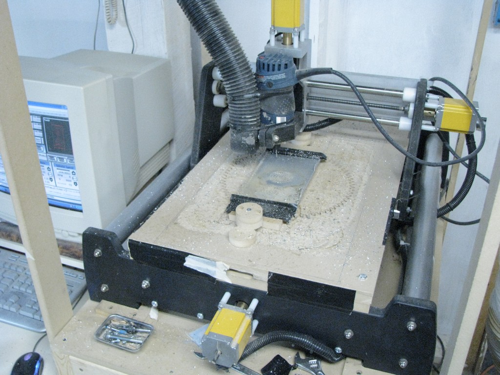
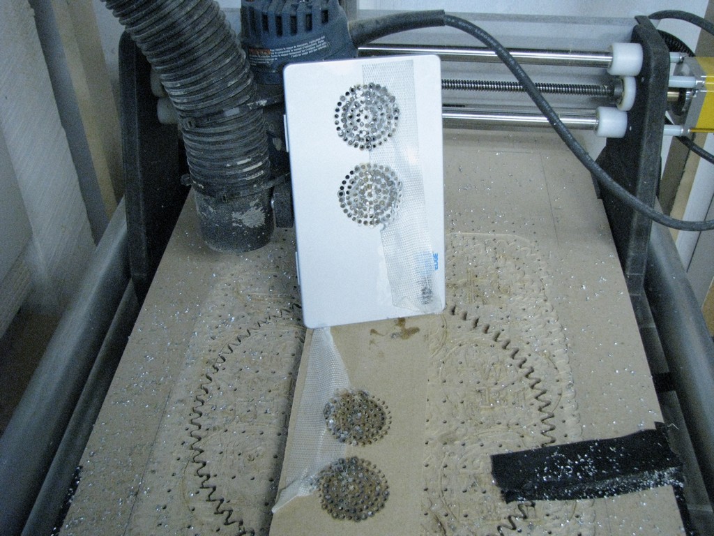
The air will enter an exit the enclosure through a series of holes. There were done on my V90 CNC machine but it could have just as easily been completed using a drill press. Ensure that there is enough holes that air can easily pass but there is still some structure.
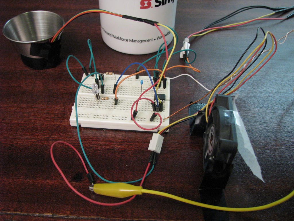
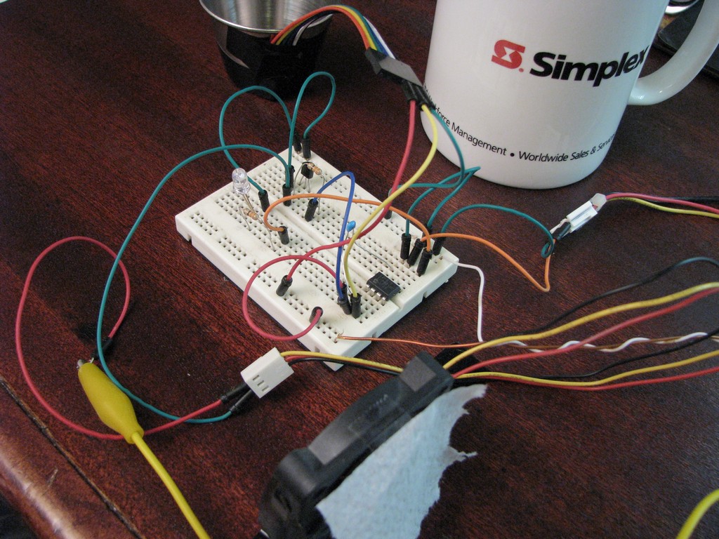
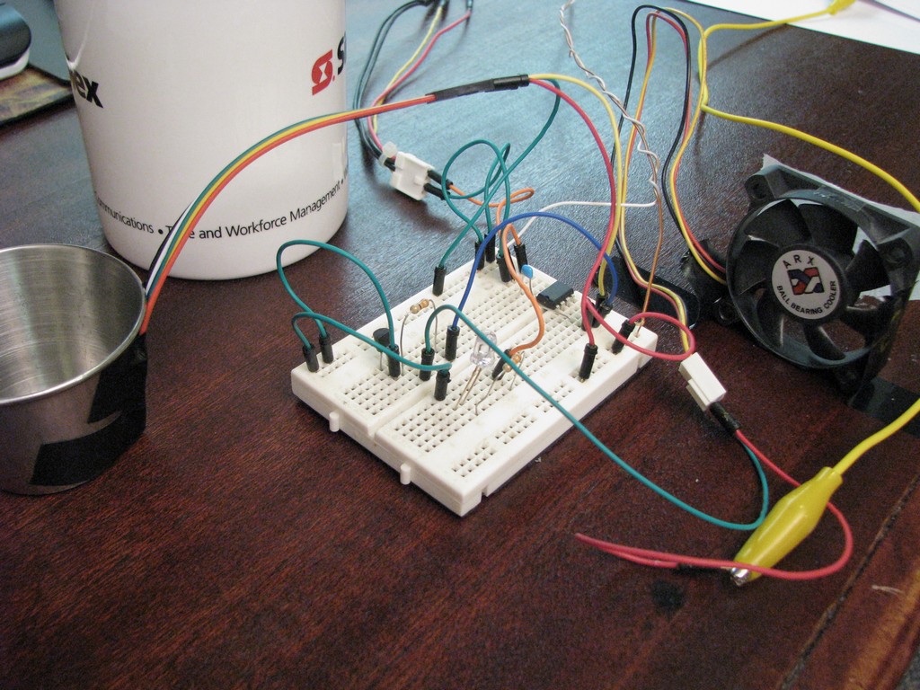
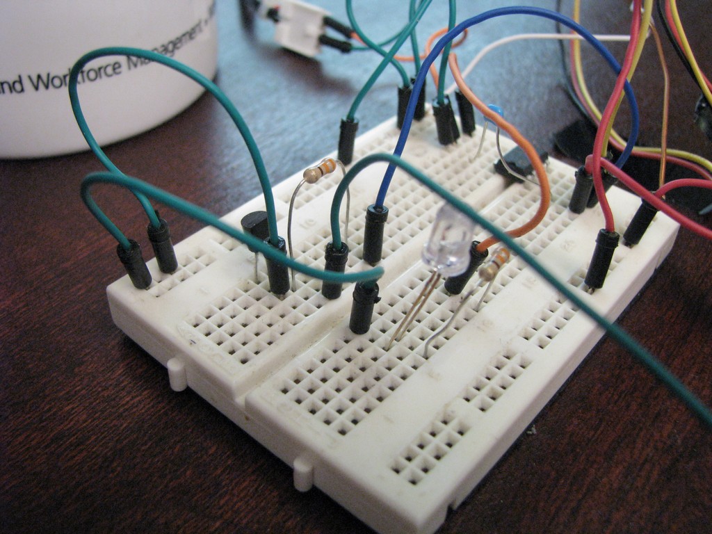
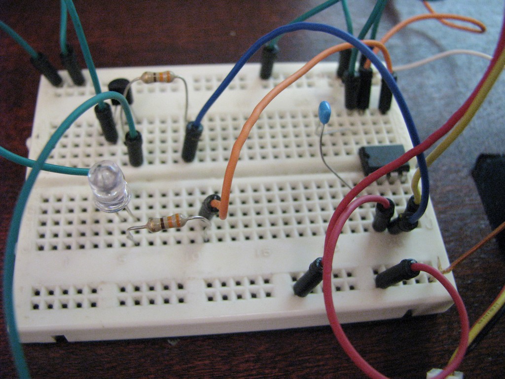
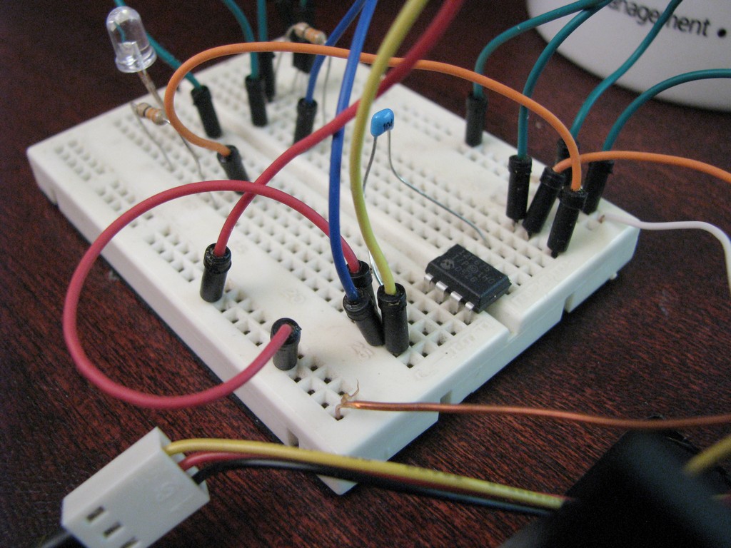
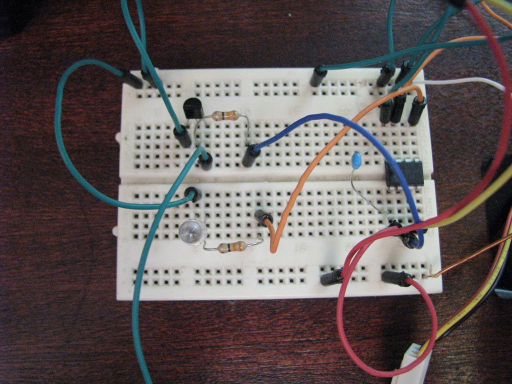
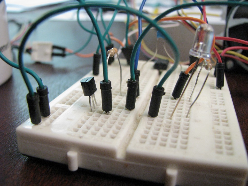
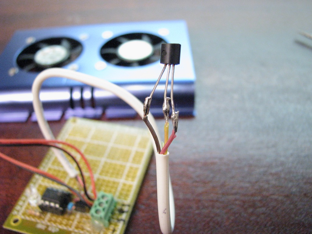
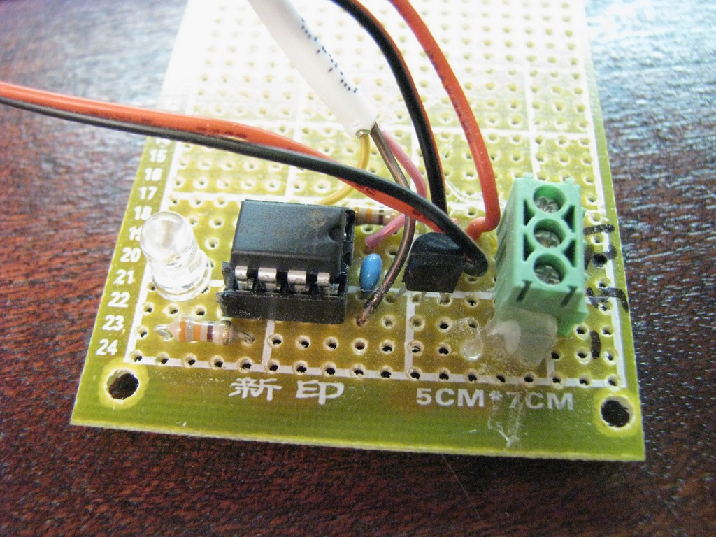
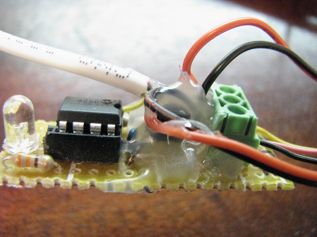
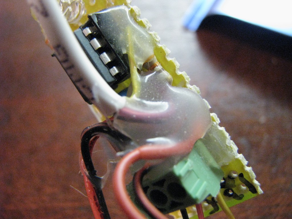
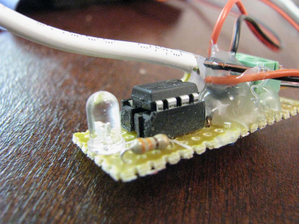
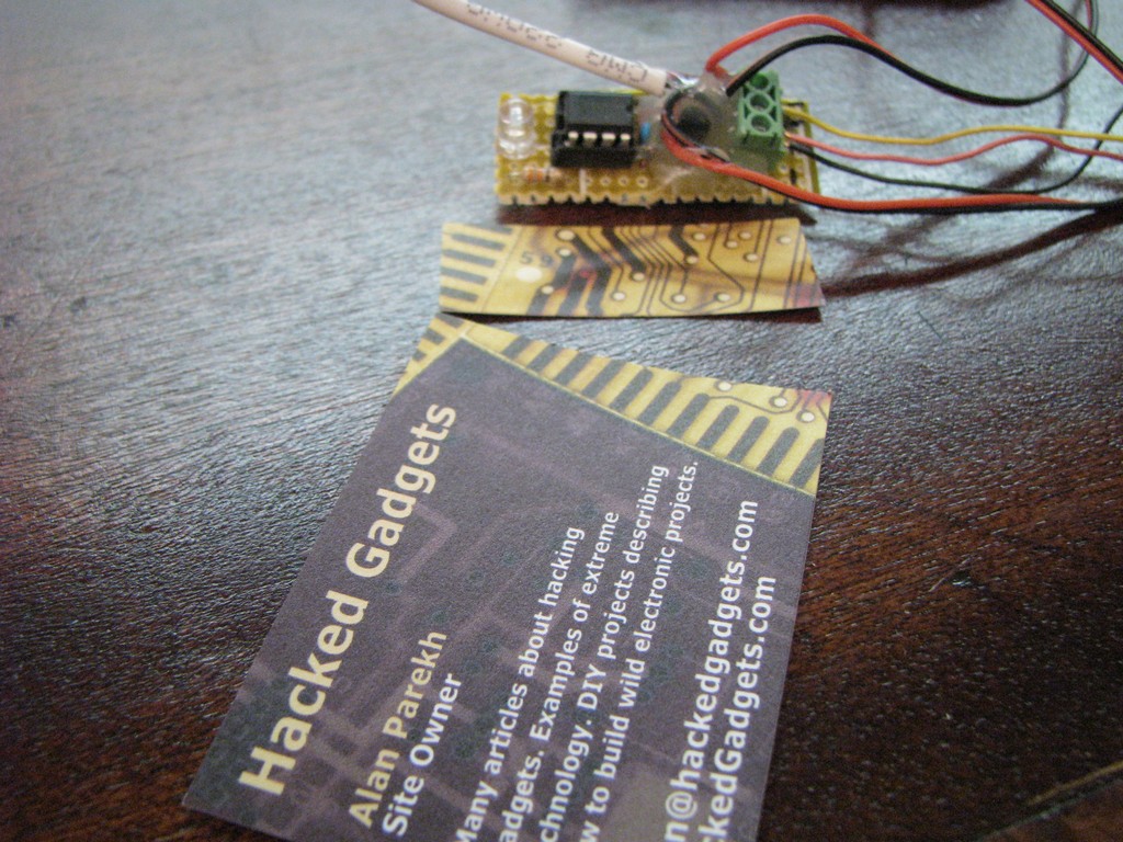
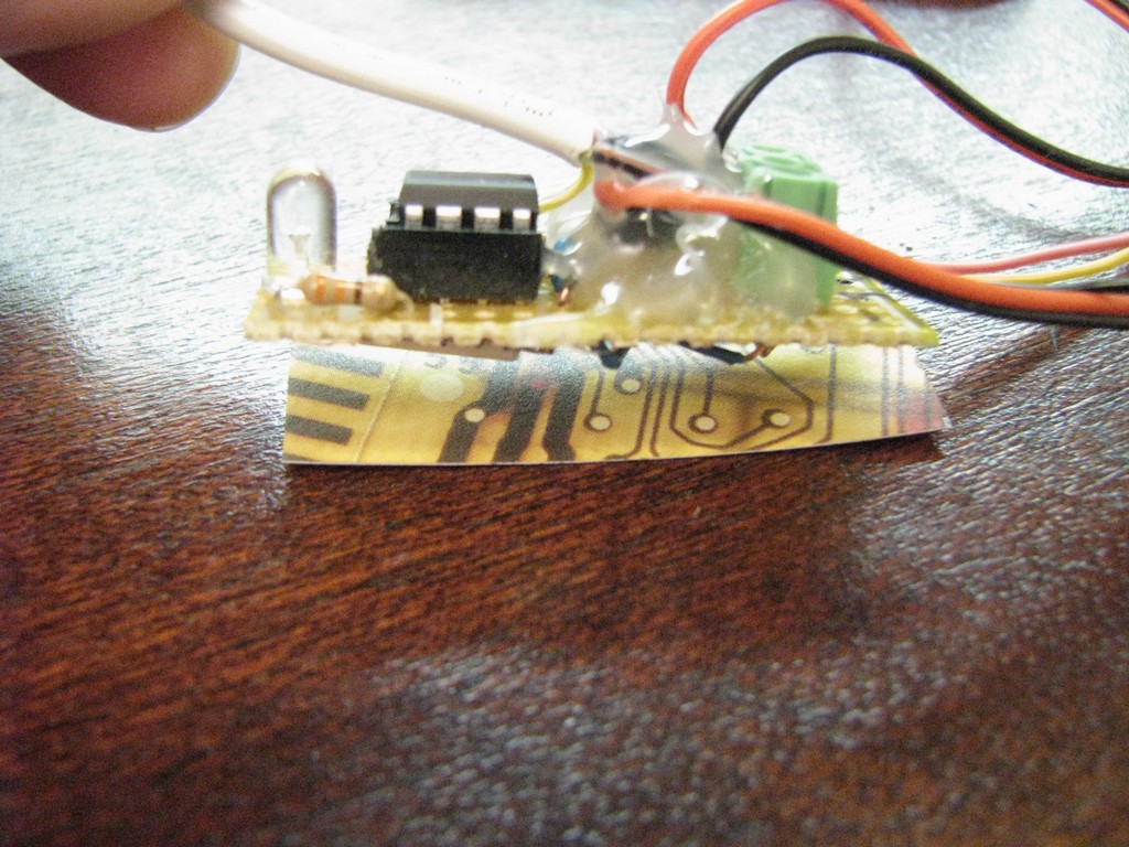
Perf Board Circuit Assembly
The final circuit was built onto a perf board. The circuit had to be kept quite small so that it would fit in the small area beside the fans in the fan enclosure. A piece of a business card was attached to the bottom of the perf board to prevent the circuit from shorting out to the metal case of the hard drive enclosure. Hot glue was used to isolate some parts of the circuit as well as providing some strain relief in other areas. Hot glue isn’t conductive which makes it perfect for these quick and dirty applications.
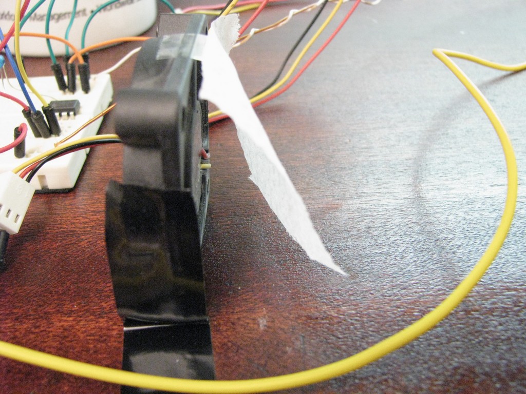
Cooling Fan
The cooling fan that is being used is a hard drive fan, it would normally be bolted to an internal hard drive and provide constant cooling. In this normal state it would always be running as long as the computer is on. In my case that was definitely not an option since the external drive is always powered up meaning the fan would be running 24 hours a day. The cooling is provided through a series of holes that were drilled into the the external hard drive enclosure. One of the fans was also turned around so that one fan would blow into the enclosure and the other would suck the hot air out.
Code
The code is very simple. A temperature reading is taken and based on the table shown in the Fan PWM Temperature Range the correct PWM value is output to the fan and the indicator LED.
Schematic

Click on the image for a large version of the schematic.
Parts
We have most of the items available in the online store.
- Pre-programmed PWM Fan microcontroller
- 0.1 uF Bypass Capacitor
- Blue LED
- 330 Ohm Resistor (2 required)
- NPN Transistor
- Perfboard
- LM35 Temperature Sensor
Download Code
If you are interested in burning your own chip you can get the HEX file here. If you would like to have a look at the source code that is available as a free item in the online store.
Pictures


on April 9th, 2010 at 2:19 pm
[…] made a PWM Fan Controller to cool my external hard drive that got quite warm when it was running for an extended period of […]
on April 9th, 2010 at 5:15 pm
This is seriously one of the best video’s I’ve seen in a LONG TIME! Please keep up the awesome work!!! MORE VIDEOS just like this, AMAZING! I’ll go and rate the video’s thumbs up on youtube as well, VERY VERY good!!!
Thank you!!!
on April 10th, 2010 at 2:00 am
[…] made a PWM Fan Controller to cool my external hard drive that got quite warm when it was running for an extended period of […]
on April 10th, 2010 at 8:24 am
Hi.
My name is Cata and i like your projects very much.
I’m trying to make a “PWM Fan Controller”.
How did u connected this PIC to PC? To do this I must modify the program that is burned in to the microcrontroller? How can i make the interface betweend PIC and PC?
Or how can i mount a Lcd display so that it shows me what temperature my hard drive has?
Thank you!
on April 10th, 2010 at 8:36 am
Hi Cata,
I didn’t go over it in detail since the final version doesn’t have it enabled. Sending serial data out to the computer takes a bit of time so during that transmission there is a bit of PWM lag. You could of course send it out once ever minute or something though.
You could connect it directly to a computer serial port or to a serial LCD.
This page goes into some of the details of wiring a microcontroller to a computer. Be careful if you do this though since computer damage can occur if something is accidentally done wrong.
http://www.tigoe.net/pcomp/code/serial-communication
on April 11th, 2010 at 1:43 pm
These are some seriously excellent videos! Thank you so much!
I have to say though, I really need to clear up on how the final circuit works. And especially how the micro-controller works. :S
on April 14th, 2010 at 10:05 am
[…] says that it was probably designed to handle the heat sufficiently, he thought it would be fun to beef it up. He’s using a pic 12f675 microcontroller as the brain and an LM35 temperature sensor. The Fan […]
on April 14th, 2010 at 3:07 pm
[…] all know just how much heat a hard drive can generate while it is in operation, and Alan decided to do something about the situation by designing a method to handle the heat efficiently. that was made possible by using a […]
on April 14th, 2010 at 3:12 pm
[…] all know just how much heat a hard drive can generate while it is in operation, and Alan decided to do something about the situation by designing a method to handle the heat efficiently. that was made possible by using a […]
on April 14th, 2010 at 3:15 pm
[…] all know just how much heat a hard drive can generate while it is in operation, and Alan decided to do something about the situation by designing a method to handle the heat efficiently. that was made possible by using a […]
on April 14th, 2010 at 3:21 pm
[…] all know just how much heat a hard drive can generate while it is in operation, and Alan decided to do something about the situation by designing a method to handle the heat efficiently. that was made possible by using a […]
on April 14th, 2010 at 3:31 pm
[…] most feverishness a tough expostulate can beget whilst it is in operation, and Alan motionless to do something about the situation by conceptualizing a process to hoop the feverishness efficiently. This was done probable by […]
on April 14th, 2010 at 3:33 pm
[…] all know just how much heat a hard drive can generate while it is in operation, and Alan decided to do something about the situation by designing a method to handle the heat efficiently. that was made possible by using a […]
on April 14th, 2010 at 6:04 pm
[…] all know just how much heat a hard drive can generate while it is in operation, and Alan decided to do something about the situation by designing a method to handle the heat efficiently. This was made possible by using a […]
on April 14th, 2010 at 6:29 pm
[…] all know just how much heat a hard drive can generate while it is in operation, and Alan decided to do something about the situation by designing a method to handle the heat efficiently. that was made possible by using a […]
on April 14th, 2010 at 9:14 pm
[…] all know just how much heat a hard drive can generate while it is in operation, and Alan decided to do something about the situation by designing a method to handle the heat efficiently. This was made possible by using a […]
on April 14th, 2010 at 10:16 pm
Just FYI, you can use the V_REF pin on the PIC12F675 to change your ADC range since you’re not using GP1 as an I/O. So instead of 0-V_DD (5V) you can use 0-V_REF. So if you can input a voltage like ~1.024V you get a clean resolution like 1mV. Not that you need that kind of precision, but it can make life simpler.
on April 14th, 2010 at 10:21 pm
Hi Jakeypoo,
Thanks for the info, I will have to look into that for future projects.
on April 14th, 2010 at 10:34 pm
[…] all know just how much heat a hard drive can generate while it is in operation, and Alan decided to do something about the situation by designing a method to handle the heat efficiently. This was made possible by using a […]
on April 20th, 2010 at 1:53 am
Great job Alan. One correction. The title of the last video is “3 of 4.” That should be “4 of 4.” It is refreshing to see such a practible application. I use a Fantom 2Tb USB drive for a weekly backup and noticed that after spinning for 16 hours it gets quite warm! (But then, who wouldn’t?) Now I have a solution. Thanks. As an addition, you might provide a link to how to program the PIC, or maybe the info is already there in your link, I didn’t check. Just a thought.
on April 20th, 2010 at 10:13 am
Alan,
Once again you’ve done a superb job! Very nice project and well displayed. Thanks again and keep up the very good work.
Roger
on April 20th, 2010 at 10:19 am
Thanks for the catch Dennis, I have corrected the video title.
on May 24th, 2010 at 7:50 am
Hello Alan, it’s a fine piece of work you made there!
I have two things to say:
1 Lots of air will flow through the big holes between the HDcase and the fanholder. Closing those holes would make your cooler far more efficient.
2 Imagine it’s very hot in the room. The fans would be at 100% all the time which is useless. It’s impossible to cool a HD down to 45° when the room is 46°. Even when the HD is idle the fans would be at 100% all the time.
You might wanna add a second temperatureprobe that measures the temp of the coolingair. That way, in the summer, by shifting the curve to the right, the fans would be at 100% for example at 53°.
I hope you get my point. I am looking for a fancontroller that takes into account the temp of the coolingair but until now I didn’t find one.
Best regards, Carlo, The Netherlands
Keep the good work up!
on May 24th, 2010 at 8:19 am
Hi Carlo,
Thanks for the feedback. You make very valid points. There are lots of areas this design can be improved.
You are right that there will be some airflow directly between the fans I was going to place a routed spacer under the fans to couple the fans to the case but was pleased enough with the cooling performance that I didn’t design and install it.
Yes, this unit would have those side effects if the room temperature air was hot. A second sensor would be a great way to solve that issue as you mention. Luckily I will be using it in an air conditioned room so it will always be around 24 to 26 degrees in here.
on June 25th, 2010 at 3:56 pm
Hi Carlo,
Very useful project. nicely presented. I am unable to downlaod the code. Please could you send me the code for the above project. I alos wanted to know how the PC is connected to chip over the serial cable.
on June 25th, 2010 at 5:21 pm
Hi Nathan,
I am assuming you meant Alan and not Carlo. 🙂
This is where you can get the source code.
http://alan-parekh.vstore.ca/product_info.php/cPath/3/products_id/108
The serial output has been disabled in the final version since it was only for testing and sending serial data takes a bit of time and would be noticeable in the PWM output to the fan.
on June 26th, 2010 at 5:28 am
Hello Alan
Very good projects!! You explain very well!!!
I am interesting to the projects. Where can i get the small fan?
Thank for your response
on June 26th, 2010 at 12:39 pm
Hi Arouna,
Thanks. You can get the fan from any computer store.
on June 26th, 2010 at 2:30 pm
Thaks John its a good project, which you introduced with me..
Everyone should try it.
on June 26th, 2010 at 3:44 pm
Hi Alan,
A wonderful project in great detail. What else one can ask for? Great for Electronics Engineering students to try and learn.
on June 26th, 2010 at 4:03 pm
Hi Alan,
I am unable to get the source code. Even after proper completion of the order as a free item I get a reply ‘Server Busy’ unable to process your request. Could you let me know how to get it please. Thanks
on June 27th, 2010 at 6:25 am
Hi S. Raju,
Thanks for the kind words. I do see your firmware order and it has now been processed. These orders are processed manually which is why you don’t get the firmware immediately.
Sorry about the server busy message. This only happens when there is a high load on the server.
on June 27th, 2010 at 2:08 pm
Thanks. You can get the fan from any computer store.
on June 27th, 2010 at 2:20 pm
Hi Alan,
Thank You. I have received the source code.
on July 16th, 2010 at 2:11 pm
Hi Alan,
I’m from Romania and i want to congratulate you for all this useful projects..
I make this project for me but unfortunately it don’t works.
Can you tell me what value i must have to PIC pins 2 and 3 ?
Can you give my the hex code for data display to PC ?
Thanks in advance!
P.S. : Sorry for my english.
on July 17th, 2010 at 9:14 am
[…] PIC18F4550 microcontroller and a Microchip MCP9701 for sensing the temperature. I used the LM35 in PWM Fan Controller project but based on what I see I think I will need to look at the MCP9701 for future projects. In the LCD […]
on July 19th, 2010 at 2:58 am
Hi Lucian,
The pins can be seen here.
http://alan-parekh.com/wp-content/uploads/2010/04/pwm_fan_controller_schematic.gif
The code to display data was never released since it was only used to test the code. The way the system generates the PWM sending temp data to the computer would cause slight speed fluctuations.
on July 27th, 2010 at 2:53 pm
[…] Fan Controller – [Link] Tags: fan, PWM Filed in Control | 1 views No Comments […]
on September 22nd, 2010 at 12:48 pm
can u give me idea for making temperature controller using 8085 microprocessor…
on September 22nd, 2010 at 12:58 pm
Hi shobhit,
I am not very familiar with that microprocessor but I believe that it doesn’t have any analog to digital inputs so that would make it a poor choice.
on March 1st, 2011 at 2:24 pm
Hi,
What about if I want to use it to control a radiator fan on my car, what kind of temperature sensor is recommended and a good transistor to handle that, thanks and keep up the good work.
on March 1st, 2011 at 4:54 pm
Hi Felix,
You could use the same sensor but you would need to find a good location for it. The temperature settings would need to be programmed to match what you need for your car. I would meter the current that the fan needs and select a transistor that can handle 5 to 10 times that amount.
on March 1st, 2011 at 10:32 pm
I will follow your instructions, Thanks Alan.
on March 2nd, 2011 at 11:16 pm
Alan, Cool project. I was screwing around with a heatsink fan and a PIC today at work. We started with a table but got carried away and wanted to try more fancy PID get the fan to regulate better at constant air temp. We have constant heat load, but ambient varies. Gave up on the ID part and just used P. I think I’ll use your approach for a temp controlled fermentation chamber for brewing. Since I started brewing I do more thinking than drinking. Thanks. I hear some Canada in you. Dont forget about that akey outpost in Northern California Hey. Go Sharks. Thank you for efforts.
on March 3rd, 2011 at 5:16 am
Hi Azimuth,
Good to hear from you. I tried the home brew route but couldn’t get a consistent tasting brew that tasted good. I am thinking that temperature has a lot to do with my poor results.
on April 3rd, 2011 at 8:21 am
can u please give me an idea for making the temperature controller using 89c51rd2 microcontroller…
on April 3rd, 2011 at 10:08 am
Hi Akshay,
Sorry, I have never used that microcontroller before.
on April 6th, 2011 at 11:29 am
Hi Alan
nice job dude
I have the same assignment . I want to increase the speed of fan while the temperature increasing.
I have two idea.
one is use different condition with different value of frequency, like if (temperature > 30 ) then pwm= 2 kh and if temperature > 35 then pwm + 4Kh, .
the second idea is to use this source code as below :
unsigned char speed=50;
if (temp>30){
CCPR1L=speed;}
else if(temp>35) //Speed Increment
{
if(speed<255)speed+=1;
CCPR1L=speed;
delay(5000);
}
else if(temp0)speed-=1;
CCPR1L=speed;
delay(5000);
else
CCPR1L=0;
do you have any advice ?
actually I am working on it but still I can’t get the expected result? if you are interested I can send you the whole code and you can help me better.
on April 20th, 2011 at 11:10 pm
Hi Alan,
Could u plz give me some details of making a temperature indicator and controller using LM35,LCD,ADC0804, 89C51 and a fan…plz try to help. i need the circuit diagram and the code for it
on April 21st, 2011 at 1:32 am
Hi Shija,
Sorry, I have never used a 89C51 before.
on April 30th, 2011 at 2:34 am
Hi Artin,
Not sure I follow your code, where does the fan get pulsed? In your language can you use a char as a number variable?
on June 29th, 2011 at 6:30 am
[…] Station Project. It uses a LM34 temperature sensor which is similar to the LM35 that I used in the PWM fan controller project except it outputs voltages that scale with Fahrenheit instead of Celsius. There is a […]
on July 24th, 2011 at 5:33 am
Hello and thank you for this idea. I already made the sistem to work but now I want to do some changes in the actual temperature values for witch tha fan will start. I tried to compile the modified .bas file but every compiler gives me errors. Can you help me with this? What compiler did you used and what version?. I opened the unmodified file from you and tryed to compile but gives me the same errors. Waiting for reply. Thanks
on August 18th, 2011 at 4:30 am
Thanks for the idea and the (extremely) thorough explanation.
I want to apply it to a media player which has an internal hdd and is equipped with a noisy fan. The fan’s purpose is to cool the hdd (the media player electronics are not disspation that much).
One question though: shouldn’t there be a suppression diode connected in parallel with the fan motor to protect the diode from inductive voltage spikes?
on August 18th, 2011 at 4:45 am
Hi Gerrit,
Sounds like a perfect application for the system. The diode would be a good thing to add to make sure there is no electrical noise coming back from the fan.
on August 19th, 2011 at 5:50 am
Hello,
first of all nice job. I also want to build a similar circuit, problem is I have more then five DS18B20 temp sensor at hand and no LM35 :(. Do you think in the near future you could implement such a one-wire device also? I suppose the circuit diagram would remain the same…
Thanks.
on August 19th, 2011 at 11:32 am
Hi Andreas,
Thanks. It is possible that a one-wire project might be implemented in the future, but at this time there is no plan to create it.
on August 28th, 2011 at 3:33 pm
Tip: you need to have a diode connected across your fan motor or you’ll have very large voltage spikes on the 12Volt line. Don’t underestimate how much that voltage can swing when the power switches off. I built a circuit very much like what you’re doing here and saw 60 volt spikes. I wouldn’t connect this to a live computer until you’ve verified it’s working ok with a good oscilloscope.
on August 29th, 2011 at 4:50 am
Hello, any advice for my problem?
Thanks in advance
on August 29th, 2011 at 2:34 pm
Hi Lician,
Sorry about that, I am quite sure I replied but I don’t see it here. The code has been written in PicBasic Pro by ME Labs.
http://melabs.com/
on September 2nd, 2011 at 2:11 am
Hi Alan,
What version of the compiler did you use? I also tried to modified it and didn’t work…
on September 2nd, 2011 at 2:14 am
I am using PICBASIC Pro 2.46A
on September 2nd, 2011 at 5:08 am
I have tried with the new version 3.0, probably that is the problem… Could I ask for a few modifications? I want to use this project in a power amplifier, and in this case the conditions change a bit. I need the fan to start at 30 degrees and at this temperature the speed should be 20% ( it’s not a problem for the fan I am using). Could you make these changes, I would really appreciate it. Thank you.
on September 4th, 2011 at 8:45 pm
Hi, How can I to use this proyect for a 12 V and 1.5 A FAN? or maybe you can help me is for a PS3 slim mod
Thank´S
on September 4th, 2011 at 10:06 pm
Hi Pablo,
You would just need to use a voltage regulator to make the 5 volts (do a Google search for LM7805) and use a mosfet transistor capable of the current you need. If your can is 1.5A I would use a mosfet that can handle something around the 5A mark.
on September 7th, 2011 at 2:11 am
I’m using a Dynatron 191 cpu cooler to cool a 100 watt LED array. It has a low profile and uses a 4-wire PWM fan. Can your controller design be modified to operate a 4-wire fan (vs. the 2-wire fans shown) and vary the speed as the LED temp changes? I’m modding a LCD projector and want to keep the fan noise down, but protect the lamp too. Thanks!
on September 8th, 2011 at 9:10 pm
Hi Charlie,
Sorry, this design doesn’t use the extra 2 wires in those fans which is used to feedback the actual speed of the fan. The controller strictly adjusts the PWM based on temperature and assumes that the fan is operating based on the PWM being fed to it.
on September 22nd, 2011 at 7:37 am
i want to do make a pwm fan controller using atmega32. what changes should i make in the source code you have provided and in the circuit??
on September 22nd, 2011 at 8:06 am
Hi Shalini,
You could use the code as a guide only in this case since whatever language you use for the atmega32 controller will be slightly different.
on October 3rd, 2011 at 1:01 am
Hi Alan,
Very useful project. I have ordered a programmed pic 12F675 from your store. When can I expect it to be delivered?
on October 8th, 2011 at 5:50 pm
[…] you are interested in building one you can see his Arduino code here. This project is similar to my PWM Fan Controller but adds a huge visual […]
on October 26th, 2011 at 12:04 am
very nice your project!!!!! congratulation!!!!!
in another opportunity can you show how to program pic step by step?
on October 30th, 2011 at 9:01 am
[…] inside a AC Ryan Media Player caused Gerrit van Donk to use the PWM Fan Controller Chip from the PWM Fan Controller Project. This will allow the fan to remain off when the unit is cool inside and only turn on when the […]
on December 7th, 2011 at 4:16 pm
Hi Alan,
I am trying to recompile the code for different temperature settings, however, I don’t have have your modefs.bas that you used for defining the serial output. Consequently I get compiler errors. Any chance you could email it?
Very much appreciated,
Stefan
on January 11th, 2012 at 8:59 pm
Hi Alan,
great video!
I have a question for you. Did you use one of the PWM of your micro controller or did you program your own PWM signal yourself?
I am working on a similar project but had limited experience with PWM and was wondering if you just used the PIC’s features or if you did something else. (I noticed most PIC have PWM out)
Again great work there!
thanks
Stephen
on January 11th, 2012 at 10:02 pm
Hi Stephen,
I just hand coded the PWM. Using the internal PWM would provide the same result with less code though.
on January 13th, 2012 at 6:27 pm
Thanks Alan
I was wondering if your code was available for download?
Stephen
on January 13th, 2012 at 6:58 pm
Hi Stephen,
You can get it here.
http://alan-parekh.vstore.ca/product_info.php/cPath/3/products_id/108
on January 13th, 2012 at 7:19 pm
fantastic, thanks!
on February 28th, 2012 at 5:29 pm
Awesome video’s, great way to explain your project and is exactly what I needed to get me rolling. Almost everything you explained can be modifed to work with my project, which is a fan controller for a rack that contains a bunch of home A/V equipment. Great job.
on April 26th, 2012 at 8:11 pm
I tried ur code(hex). but, that’s confusing. I’m familier with assembly. can u help me………….. how to convert hex file into asm.
on April 26th, 2012 at 8:16 pm
Hi Amila,
Get the source code here.
alan-parekh.vstore.ca/index.php/cName/source-code
on May 5th, 2012 at 2:38 pm
hello
you have the ASM code because I would like to change the temperature 30 to 100 degrees celcius.
thank you
on May 6th, 2012 at 2:19 pm
Hi Peter,
Unfortunately the only code that was made was for the temperatures in the project.
on June 12th, 2012 at 1:19 am
I wanna do this program myself. how we begin to write the program. I use assembly to do that. As i know first we must insert a value to PR2. If we want to get 30% pwm @ 40C, how to begin select registers and register values for that. I’m looking for your great help.thank you
on June 12th, 2012 at 2:23 am
ok. I got few steps. first we select oscillating frequency. then,make ccp1con for PWM mode.then select values for PR2 & T2con for calculate PWM frequency.then clear TMR2. then calculate values for CCP1L & CCP1CON values for considered duty cycle .Then start timer2.Am I correct? If I correct how to develop this method for two or more steps.
on June 12th, 2012 at 7:40 am
is this correct. if this is correct how to go on
;2.5kHz PWM frequency with 75% duty cycle
portc equ 07h
trisc equ 87h
ccpr1l equ 15h
ccpr1h equ 16h
ccp1con equ 17h
tmr2 equ 11h
t2con equ 10h
pr2 equ 92h
pir1 equ 0ch
;
list p=16f877A
;
org 0x00
;
clrf ccp1con
movlw D’249′
movwf pr2
movlw D’186′
movwf ccpr1l
bcf trisc,2
movlw 02h
movwf t2con
movlw 3ch
movwf ccp1con
bsf t2con,2
again bcf pir1,1
loop btfss pir1,1
goto loop
goto again
end
on September 25th, 2012 at 12:44 am
Please how do you obtain the serial output of the raw data, calculated temperature and the pwm value? thank you.
on September 25th, 2012 at 12:52 am
Hi Abdullahi,
There is no simple way other than enabling it in code. The way the PWM was done it will be less smooth with it turned on.
on October 1st, 2012 at 2:07 am
Thanks for the explaining . After enabling it in code, so how do I obtain the serial output via the RS232 connector to be seen on the monitor screen showing the raw data, calculated temperature and the pwm value as shown in your video no.2.
Thank you
on October 1st, 2012 at 2:15 am
The serial temperature data will be outputed on pin GPIO 0. You would need to run a terminal program on your computer. Then you simply connect the serial output of GPIO 0 into your computer and tie the ground of the circuit to the ground of the RS232 connector.
on October 12th, 2012 at 1:57 am
Hi Alan,
Can i know what software are you using to display the data at computer?
thank you
on October 12th, 2012 at 2:31 am
Hi Andreas,
The code is written in PicBasic Pro
on November 14th, 2012 at 2:37 pm
Hello Alan,
God bless you for your kindness which guided to share this project with all of us!
I’m looking for some time on web, hopping to find something similar…because I’m trying to develop 2 projects: one is replacing my car’s mechanical engine fan with a electric one and second is to made “heated” mirrrors, also based on temperature sensor.
on November 25th, 2012 at 5:01 pm
Hey i’m working on a project now to give a quick response on quality and fault diagnose of an internal combustion engine can you please advice on a kind of chip to use and a circuit diagram for it Thank you.
on November 26th, 2012 at 4:01 am
hi. Can you send me the codes and relevant details of this project? I really want to make this as my project in one of our subjects. Can you send it to my email? johnmark.batabat@gmail.com . Thanks. If you have the codes written using the pic16f877a, it is much appreciable. Thank you.
on November 26th, 2012 at 3:25 pm
Hi Alan,
This is a pretty cool project. I’m building one to force air through my entertainment center which gets hot when my equipment inside is turned on. I’d like one sensor to turn on a couple of fans. I can’t see on the pictures of your circuit board. Are you running two fans by connecting the output of the PIC to the collector of two transistors each switching one fan on and off, or do you have the fans in parallel hooked up to one transistor? Would either set up work (assuming the transistor was rated high enough for multiple fans)?
Thanks
on November 29th, 2012 at 6:50 am
Hi
Ive been searching the web trying to find a pwm fontroller that will vary the fan speed baised on a temp sensor
Ive had no luck until I found this page.
I have a Battery (12vdc) that I need to keep cool (AGM) its getting too hot in its location and sgoing to fail (they dont like to get too hot)
But also dont want to have the fan going unless its nessary.
The fan that I was thinking of using is something like this
http://www.ebay.com/itm/NEW-Delta-12V-PWM-120mm-fan-1-5K-5-5K-RPM-252-CFM-BEAST-/130520102730?ssPageName=ADME:X:eRTM:US:1123
Do you know of a comercially available product ?
If Not, How much would you charge me to build one ?
Thanks Shaun
shamck2 at hot mail . com
on December 17th, 2012 at 12:05 pm
Hi,can you send me complete details of this project.I like it and I want to do it as my college mini project.
on December 17th, 2012 at 4:45 pm
Hi Venkatesh,
All of the info should be on this page. What are you looking for?
on December 17th, 2012 at 4:46 pm
Hi Shawn,
That fan should be fine, you would just need to use a larger transistor since the one we use would not be able to power that size of fan.
on December 21st, 2012 at 8:47 am
Hey Alan,
I’m trying to build your PWM fan controller but I’m running into some problems. When I set up the circuit, the light and fan are always on. It doesn’t depend on temperature and I know the temperature sensor is working. Also where does the ground/negative of the 12 volt supply go?
Thanks
on December 21st, 2012 at 8:57 am
Hi Alan,
Can a 6 V supply be used to power the chip for this project?
Thanks
on December 21st, 2012 at 11:37 am
Hi Faraaz,
Use a multimeter to measure the temperature voltage being fed into the chip. Sounds like either your PIC isn’t powered or it isn’t getting the correct voltage from the temperature sensor..
The negative of the 12 volt gets connected to the negative of the 5 volt supply. This would be done within the power supply already if you are using a computer power supply.
on December 21st, 2012 at 11:37 am
Hi Syed,
No, 6 volts will damage the PIC microcontroller.
on December 27th, 2012 at 2:47 am
Hi,
Please which terminal program will be suitabe to run on the computer.
Thank you.
on December 29th, 2012 at 7:45 am
Hi Abdullahi,
You can use the one that comes with windows. You will need to recompile the code to turn on the serial output. It was only used for debugging and demonstration though so it does interfere with the fan operation as currently coded.
on January 7th, 2013 at 12:41 am
Hi Alan,
My temperature sensor is sensing the heat, the LED blinks and goes off when it cools . Surprisingly the fans which I have connected to a 12V dc power supply aren’t coming on. What seems to be the problem ?
Thank you.
on January 8th, 2013 at 2:35 pm
Hi Abdullahi,
Is the positive lead of the motor connected to 12 volt positive?
Alan
on January 21st, 2013 at 12:14 am
Hi Alan,
Thank you for this wonderful project! I tried out your circuit and it worked with one fan but I used 2N222A for the transistor since the one you used is not available. Can you help me in modifying this circuit so I could use around 4 fans? 2 fans are already not working.
Thank you and good day!
on January 21st, 2013 at 12:19 am
Hi Nicole,
Please let me know how much current all 4 fans need. Sounds like you will just need a larger transistor to handle the current.
on January 22nd, 2013 at 12:01 am
Hi Alan,
3 of the fans that I’m using has a current rating of .22 A and 1 is .25 A. Sorry, I’m new at this and thank you very much for your help.
on February 6th, 2013 at 5:30 am
Hi Alan,
I’m a newbie in programming i want to work with this project because it looks so awesome and i can use it in many ways. Can you please teach me how did you make the codes in you micro controller and how did you burn it? please siree? Im begging you
on February 6th, 2013 at 5:47 am
Sir Alan, in addition i want to learn how did you make the whole program 🙁 and when i download your hex file in the above link is that it really should look like? lots of numbers? i thought it should look like a program? please help me siree
on February 7th, 2013 at 7:34 pm
Hi Alan,
Siree, can i have a copy in of the codes in notepad? please? I’m really fascinated of your project but i dont know how to start the programming part. please help me
on February 8th, 2013 at 3:52 pm
Hi Jabara,
Sure, there is a link to the code location in the article. When you get it just open it with notepad (it is all just text).
on February 9th, 2013 at 12:58 pm
Hi Alan,
Siree im sorry but everytime i open the download link of your hex file it only appears in numbers. Siree, can you please send me the codes copied in notepad? jabara16@yahoo.com that is my email please siree. Please help me sir i really wanted to learn how did you program this one. Thank you. God bless!
on February 10th, 2013 at 7:58 pm
Hi Alan,
Ow i get the codes now sorry, my bad. Thank you again. Your project really rocks man! God bless!!
on February 17th, 2013 at 10:12 am
Hi Alan,
can i ask for a little favor? If any instance do you have the code programmed in C language? can i have a copy of that? please?
on February 17th, 2013 at 12:51 pm
Hi Jabara,
Sorry there is no C version.
on February 25th, 2013 at 3:57 am
Hi, I would just like to clear out some things regarding your project. I am using 8 fans and paralleled 8 transistors (IRF520) and the circuit works. But after I added a voltage regulator (L7805), the fans turn on for about 5-8 seconds the instance I turned on the power supply. Where can this “leakage current” possibly comes from? I’m just curious, the circuit still works perfectly. Thanks!
on March 1st, 2013 at 10:50 am
Sir Allan, can i ask a liitle favor? can you please add in your code that when the temperature reached 50degrees celcius the fan will off? please sir? kindly send me the new hex file and even the new codes at jabara16@yahoo.com
on March 11th, 2013 at 9:40 am
sir i like your project the same am implementing as my miniproject in this am using picaxe and ds1820 temp sensor ,please help me,and give me some referrences….
on March 24th, 2013 at 3:21 am
Hi Alan,
I’m really impressed with your concept. I wish to make a similar project but using op-amps in controlling the speed of the fan, and also using two seven segment displays to display the temperature.
Can you please suggest how to display the temperature without using micro-controller.
on April 11th, 2013 at 1:39 pm
Sir,
Is there a possibility to use this project for controlling efan in a car (with AC, ignition on/off)?
on May 7th, 2013 at 8:56 am
Hi Allan
Q1: What is PWM frequency? Assuming “Fan PWM Value” (30,40,50-100%) is PWM Duty cycle.
By Intel spec is 25 KHz.
Q2: Probably, only way to set another temp range is to recompile you source, right?
on May 16th, 2013 at 5:06 am
Yes, you would need to recompile to adjust the temperature range. Not exactly sure what the frequency is off hand, if humming or buzzing is your concern, it doesn’t make the fan motors buzz or hum.
on May 31st, 2013 at 4:25 pm
Great project that I found on Youtube! Thanks for shareing your expertise!
I am wanting to connect a PWM fan ( 4 wire) to a video card which already supports its own PWM ( 4 wire) fan. My idea was to just use the PWM line from the video card to the extra fan and use 12v and ground from a separate power source (PSU), thus not burdening the video card with powering multiple fans.
The question is, what of the “tach”/ sensor wire of the PWM fan? The GPU will be using the tach of its own fan, but will not know of the other fan. The feedback will be incomplete. Should this work as expected?
on July 24th, 2013 at 1:37 pm
Hey, Alan….
Thanks alot dude…i just burned your hex code and its magic for me :p…. i need this for my Inverter Box and you really helped me….
thanks alot dude…
on August 12th, 2013 at 5:54 pm
love the project , thinking of doing it myself , but i need a transistor that can drive a 5 amp fan , and was wondering what transistor do you suggest that will work witht he switching output volatge of the pic chip
on August 18th, 2013 at 3:55 pm
damn, YOU’RE A PROFESIONAL GUY!
I want a controller like this!
How much would it cost?
cheers
on November 24th, 2013 at 9:41 am
pls hw can i use it to control an AC fan
on November 25th, 2013 at 2:59 am
Hi,
Great project! I’ve built this and ran into a few issues… The LM35 was soldered directly to the board. When the fan had been running legitimately ( game console in cabinet produces a lot of heat), it would never stop completely afterwards. It turns out the transistor was producing heat of it’s own and kept the fan going for sake of keeping the fan going 🙂 Took the lm35 off and connected it through some wires. Solved.
The PWM procedure caused my fan to make quite a racket. So i replaced it with the pwm command.. shorter and makes for a way smoother fan!
Thanks for this project, it was a fun experience.
on February 1st, 2014 at 12:32 am
Hi Alan,
Thanks for the project. I plan on adding your fan controller to a retro video game emulator that I have built. Unfortunatly I cannot find a reliable source for the LM35DZ now that its not made. Do you think that the LM35DZ/NOPB would work?
on February 1st, 2014 at 1:19 am
Hi Mark,
This circuit is only for DC motors.
on February 1st, 2014 at 1:19 am
Hi gowriel,
Depends on what you need. All of the parts are available in the store.
on February 1st, 2014 at 1:20 am
Hi jeremy adams,
Yes, but you would need to change out the transistor to a larger device. I would suggest a nice big mosfet.
on February 1st, 2014 at 1:21 am
Hi tahitiansoul,
Sorry, not sure what an efan is.
on February 1st, 2014 at 1:23 am
Hi Biswarup,
The design would be completely different, I would google it since I am sure there will be some examples like that out there.
on February 1st, 2014 at 1:23 am
Hi SADANAND PATIL,
Sorry I have never done and Picaxe programming…
on February 1st, 2014 at 1:25 am
Hi Abbie,
You should just use a single large mosfet since the base current of all those transistors are probably too much for the PIC to output.
on February 1st, 2014 at 1:25 am
Thanks Jabara!
on February 1st, 2014 at 1:29 am
Hi Scott,
Not sure but we have the regular ones back in stock now.
on February 23rd, 2014 at 8:44 am
[…] […]
on March 18th, 2014 at 6:14 pm
Can you give a schema for a 1a fan,
on March 18th, 2014 at 11:44 pm
Hi Theo,
Use a mosfet that can supply 1 amp and be biased by voltage of 5 volts.
on July 1st, 2014 at 8:37 am
Best PWM project. Thank you for sharing your projects with us. I like your PWM fan controller and I’d like to build one. Unfortunately I’m still very green to PIC programing and I was wondering if it is possible to increase output PWM frequency to 25kHz and increase the temperature zone between 30 °C and 45 °C. I’ve downloaded your source code and I’m not sure what to change to increase the frequency and modify the PWM value according to my temperature zone. Can you please help me. I,m willing to pay for your help. Thank you!!!
on August 15th, 2014 at 6:12 am
Hi Allan
I have just put it togehter and put the LM35 directly on the harddrive and works very nice.
Pic 12f675 can I use pic12f683 to I have many of these
on August 19th, 2014 at 12:11 pm
Hi Allan
I have just made this project and it works nice, very good
I have no more pic 12f675 but plenty of 12f629 can I use that instead
on October 3rd, 2014 at 3:28 pm
Hi Alan,
im trying to make a circuit that will increase the existing fan speeds by 50 % for my xbox 360 slim which gets really hot . any idea how to code the hex ?
thanks
Nick
PS Great videos
on January 31st, 2015 at 10:29 am
Hi Alan; This is an awesome project – great job! Can this set-up be used to regulate a fan with an actual PWM circuit in it? If so, how would it connect up? The PWM fan has a RPM signal wire – how/where would that connect?
thanks
Paul
on February 4th, 2015 at 9:10 am
how much money did you spent?all in all.